1. Reference problem#
1.1. Geometry#
The system is composed of a set of 2 springs, 3 point masses, supported by 2 supports:
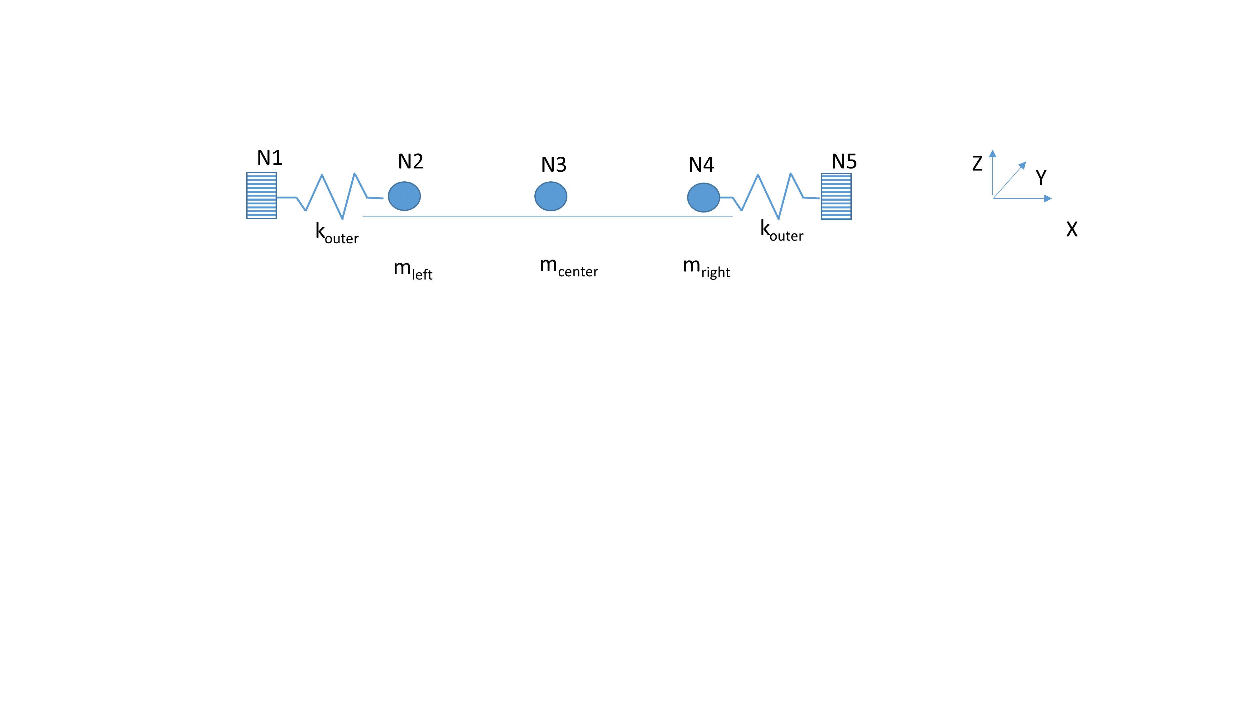
Figure 1.1-1
The system consists of the following elements:
a central mcenter mass of 10.0 kg at point N3;
two mleft and mright masses of 4.5 and 3.7 kg respectively, fixed through two elastic springs each with a kouter stiffness of 103 N/m.
The system is unidirectional, the masses only « slide » in the X direction.
The coordinates of the points shown in the figure above are:
Node |
X (m) |
Y (m) |
Z (m) |
N1 |
0.0 |
0.0 |
0.0 |
N2 |
0.1 |
0.0 |
0.0 |
N3 |
0.2 |
0.0 |
0.0 |
N4 |
0.3 |
0.0 |
0.0 |
N5 |
0.4 |
0.0 |
0.0 |
Table 1.1-1
The masses are linked together by various phenomena and devices characterized by non-linear behavioral relationships.
1.2. Boundary conditions and loads#
Boundary conditions:
All the knots in which the weights are carried are free only in the X direction: \(\mathit{dy}=\mathit{dz}=\mathit{drx}=\mathit{dry}=\mathit{drz}=0\)
Nodes \(N1\) and \(N2\) are embedded: \(\mathit{dx}=\mathit{dy}=\mathit{dz}=\mathit{drx}=\mathit{dry}=\mathit{drz}=0\).
Loading:
The central mass is subjected to a time-based sine force (monofrequency) in the form: \(A\mathrm{sin}(2\mathrm{\pi }ft)\). The amplitude \(A\) and the frequency \(f\) differ according to the modeling in order to ensure that the loading level is sufficient to activate the non-linear relationship between masses. The loads for the various models are given in the following table:
Modeling |
\(A\) (N) |
\(f\) (Hz) |
A |
60.0 |
2.0 |
B |
500.0 |
2.0 |
C |
500.0 |
2.0 |
D |
500.0 |
2.0 |
E |
50.0 |
2.0 |
F |
10.0 |
4.0 |
G |
10.0 |
4.0 |
Table 1.2-1 |
||
The total loading time is 1.0 sec. The integration is carried out with a fixed step of 1.0E-6 sec. |
1.3. Initial conditions#
The system is at rest.