1. Reference problem#
1.1. Geometry#

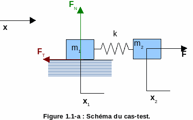
Figure 1.1-a : Diagram of the test case.
1.2. Material properties#
The two masses are the same and equal \({m}_{1}={m}_{2}=m=5\mathrm{kg}\). The stiffness placed between these masses is \(k={10}^{4}N/m\).
1.3. Boundary conditions and loads#
The masses \({m}_{1}\) and \({m}_{2}\) move along \(\overrightarrow{x}\) only.
The modulus of normal force \({F}_{N}\) is constant equal to \({F}_{N}={10}^{4}N\).
Mass \({m}_{1}\) is affected by a contact — friction condition. The coefficients of friction 5 are:
in the static case: \({\mu }_{S}=\mathrm{0,3}\),
in the dynamic case: \({\mu }_{D}=\mathrm{0,2}\).
In this modeling, the system goes through three phases:
An adhesion phase, during which the force exerted on mass \({m}_{2}\) is constant: \(F=3\cdot {10}^{3}N\).
A sliding phase, starting at \({t}_{1}\), when the tangential force can no longer compensate for the tensile force exerted by the spring on \({m}_{1}\). After an arbitrary time (\({t}_{2}=\mathrm{0,2}s\)), the force imposed is set to 0 and the kinetics of the system then tends to 0.
A second phase of grip, starting at \({t}_{3}\), when the speed of the \({m}_{1}\) mass is cancelled out.
1.4. Initial conditions#
At time \(t=0\), both masses are at rest (zero displacement and zero speed).