1. Reference problem#
1.1. Geometry#
1.2. Material properties#
1.2.1. Material 1#
Young’s module |
\(E=6\times {10}^{12}\mathit{Pa}\) |
Poisson’s Ratio |
\(\nu =0.2\) |
1.2.2. Material 2#
Young’s module |
\(E=1\times {10}^{11}\mathit{Pa}\) |
Poisson’s Ratio |
\(\nu =0.3\) |
1.2.3. Material 3#
Young’s module |
\(E=2\times {10}^{11}\mathit{Pa}\) |
Poisson’s Ratio |
\(\nu =0.2\) |
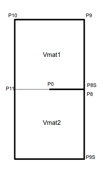
1.3. Boundary conditions and loads#
Points \(\mathit{P8}\) and \(\mathit{P8S}\) are used to apply force \({F}_{Y}\).
The lip of the crack is line \(\mathit{P8P0}\). So \(\mathit{P0}\) is the crack front.
For all the calculations carried out, the same movements are imposed.
Imposed displacement:
Embedding on side \(\mathit{P8P9S}\) |
|
Embedding on side \(\mathit{P8SP9}\) |
|
Embedding node \(\mathit{P11}\) |
|
According to the calculations, 2 types of loading are imposed:
Imposed loading:
Pressure distributed over line \(\mathit{P0P8}\) |
|
Pressure distributed over line \(\mathit{P0P8S}\) |
|
Or:
Nodal force on the GROUP_NO \(\mathit{P8}\) |
|
Nodal force on the GROUP_NO \(\mathit{P8S}\) |
|