6. D modeling#
Calculate with CALC_G and POST_K1_K2_K3 in 3D for modes 1 and 3.
6.1. Characteristics of modeling#
The following boundary conditions are applied successively:
traction: as for modeling B;
twisting.
This modeling makes it possible to test the calculation of \(\mathrm{K1}\) and \(\mathrm{K3}\) combined using POST_K1_K2_K3 (method for extrapolating movements on the lips of the crack).
The middle nodes of the edges of the elements touching the bottom of the crack are moved to a quarter of these edges, to obtain better precision.
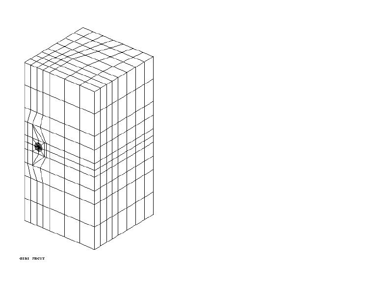
6.2. Characteristics of the mesh#
Number of knots: 6536
Number of meshes and type: 432 PENTA15 and 987 HEXA20
The middle nodes of the edges of the elements touching the bottom of the crack are moved to a quarter of these edges, to obtain better precision.
6.3. note#
Both load cases (traction and torsion) are taken into account. It is therefore necessary to combine the values of \(G\) for both loads.
So
\(G(s)\mathrm{=}(11.586+7.356)\mathrm{=}18.943J\mathrm{/}{m}^{2}\)
Only traction contributes to \(\mathrm{K1}\), only twisting contributes to \(\mathrm{K3}\).
6.4. Tested sizes and results#
Identification |
Method |
Location |
Location |
Reference Type |
\(\text{\%}\) Tolerance |
G |
CALC_GLegendre |
Node 49 |
18.94 |
|
3.0 |
G |
CALC_GLegendre |
Node 1710 |
18.94 |
|
2.0 |
G |
CALC_GLegendre |
Node 77 |
18.94 |
|
3.0 |
K1 |
|
Node 49 |
1.596 106 |
|
1.0 |
K1 |
|
Node 1710 |
1.596 106 |
|
1.0 |
K1 |
|
Node 77 |
1.596 106 |
|
2.0 |
K3 |
|
Node 49 |
1.064 106 |
|
2.0 |
K3 |
|
Node 1710 |
1.064 106 |
|
2.0 |
K3 |
|
Node 77 |
1.064 106 |
|
1.0 |
G |
POST_K1_K1_K3 |
Node 49 |
18.94 |
|
2.0 |
G |
POST_K1_K1_K3 |
Node 1710 |
18.94 |
|
2.0 |
G |
POST_K1_K1_K3 |
Node 77 |
18.94 |
|
2.0 |