3. Modeling A#
3.1. Characteristics of modeling#
For surface elements, DKT elements are used.
For line elements, POU_D_E elements (Euler-Bernoulli beams) are used.
3.2. Characteristics of the mesh#
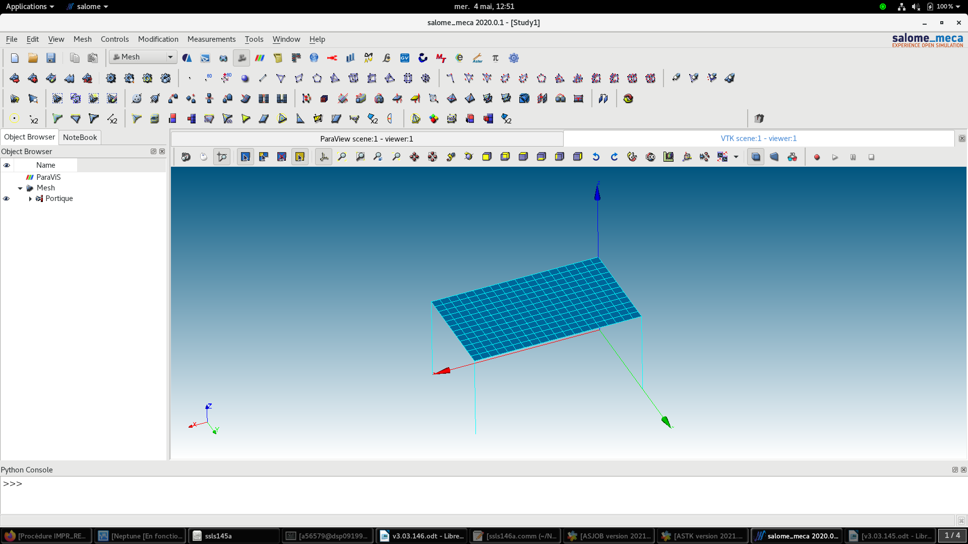
The mesh uses quadrangles for the slab and segments for the columns.
3.3. Tested sizes and results#
The values tested relate to cells in the same position (x, y) of each floor on the different floors. It is proposed to test the values of the reinforcement field obtained at two points:
Center of the slab (Point designated by “M”)
Support for Post A (whose coordinates coincide with the origin of the global reference frame of the study)
For the point “M”, it is proposed to evaluate, for the various 7 calculation combinations (as well as for the two additional configurations” COMB_DIME_ACIER “and” COMB_DIME_ORDRE “), the DNSXI component of the reinforcement field.
For point “A”, it is proposed to evaluate, for the various 7 calculation combinations (as well as for the two additional configurations” COMB_DIME_ACIER “and” COMB_DIME_ORDRE “), the AZI component of the reinforcement field.
In particular, for the measurements at the level of the support A of the column, we note an inability of the reinforcement calculation algorithm to result in a reinforcement with a dimension of ELS (corresponding to the values” -1 “). This is due to the fact that, as the column is stressed by Deviated Flexion, the method currently implemented is an iterative algorithm based on the verification of the Bresler inequality.
We are aware that this is a “simplified” method and that has its limits, as can be seen from the measures above. One way to improve the reinforcement calculation operator will be to introduce a direct and deterministic reinforcement calculation method for the case of deflected bending (with an inclined neutral axis).