1. Reference problem#
1.1. Geometry#
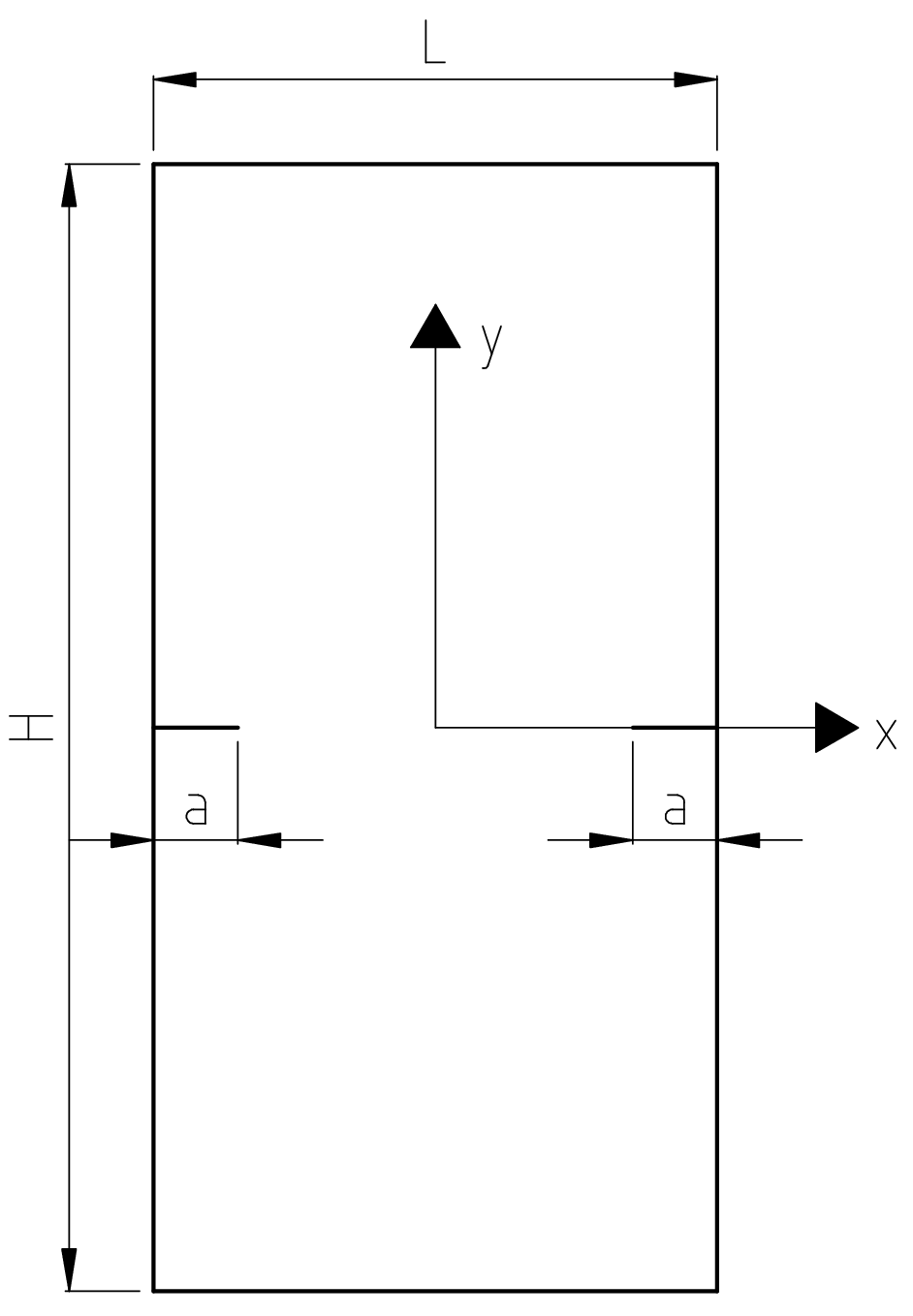
Figure 1.1-a : geometry of the cracked plate
Geometric dimensions of the cracked plate:
width |
\(L=1000\mathrm{mm}\) |
height |
\(H=2000\mathrm{mm}\) |
Initial crack length: \({a}_{0}=300\mathrm{mm}\).
The cracks are positioned in the middle of the height of the plate (\(H/2\)).
1.2. Material properties#
Young’s module \(E=206000\mathrm{MPa}\)
Poisson’s Ratio \(\nu =0.33\)
1.3. Boundary conditions and loads#
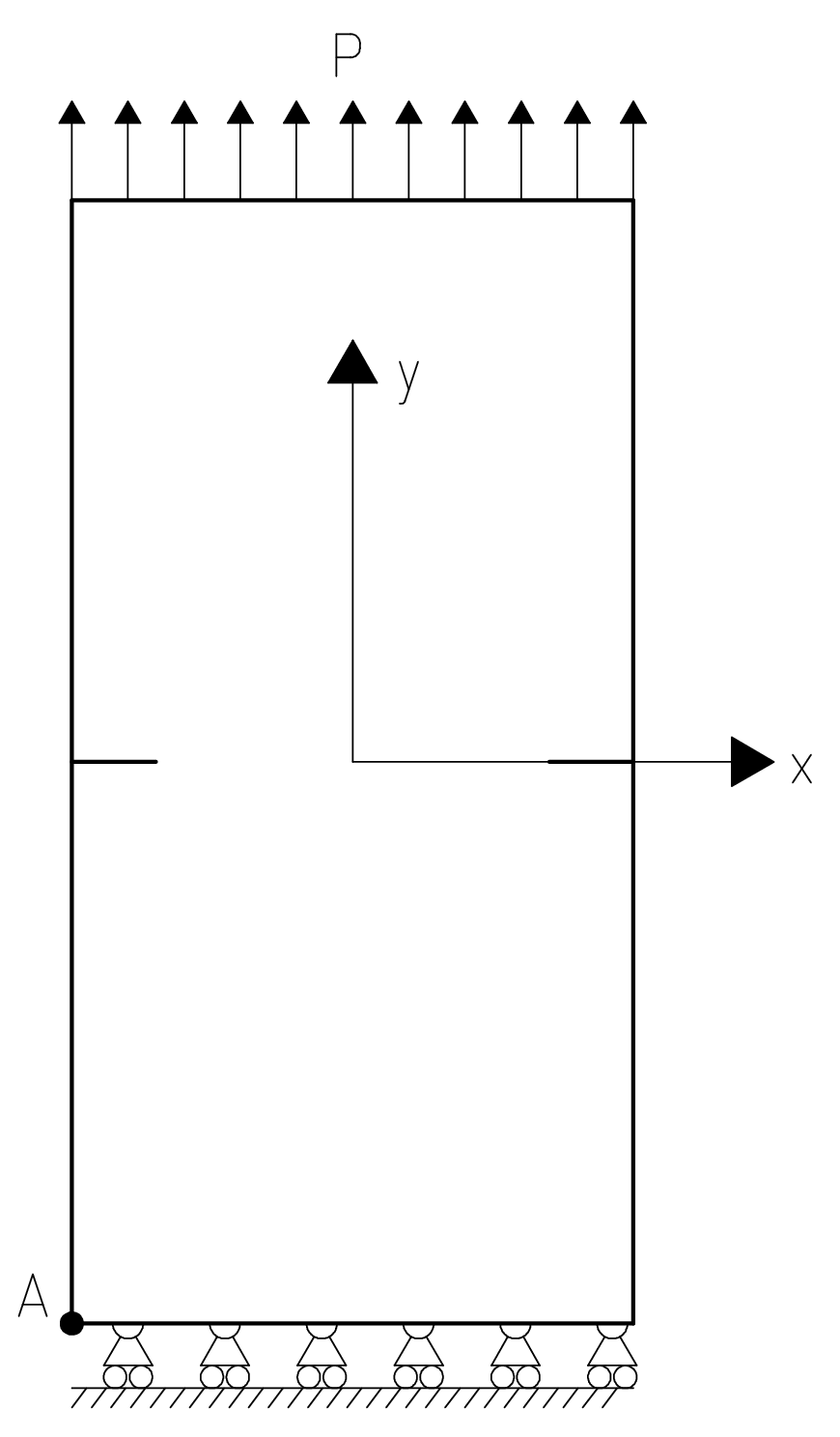
Figure 1.3-a : boundary conditions and loads
Boundary conditions:
Point \(A\): \(\Delta X\mathrm{=}\Delta Y\mathrm{=}0\)
Points on the lower end of the plate: \(\Delta Y\mathrm{=}0\)
Loading:
Pressure applied to the upper end of the plate: \(P\mathrm{=}1\mathit{MPa}\)
Three propagations are calculated by imposing a maximum crack advance equal to \(30\mathit{mm}\). As a result of the symmetry of the geometry, the boundary conditions and the loading, the advances of the two cracks are always equal to the maximum advance imposed.