6. D modeling: FEM, whole plate, radiant mesh#
A mesh radiating around the point of the defect is used. The radiating part corresponds to a disk with radius \(a/10\). This disk consists of 8 layers of elements of constant thickness. So the thickness of a layer is \(h=a/80\). Views of the mesh are given in the figures below. The mesh used for the calculation is quadratic, with Barsoum elements.
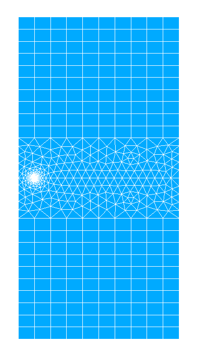
Figure 6-1: Full view of the radiating mesh of the plate
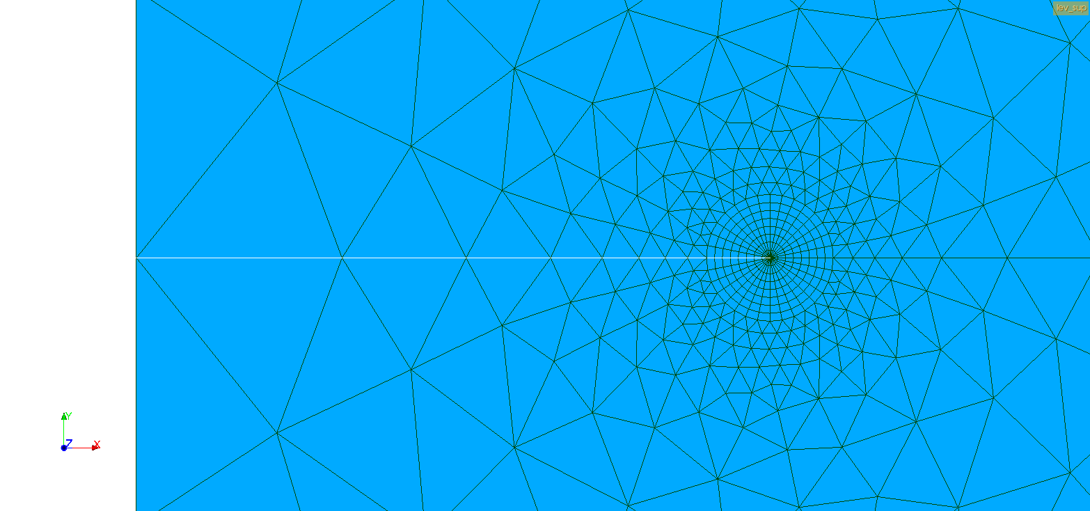
Figure 6-2: Zoom in on the crack
Boundary conditions and loading are the same as those defined in modeling A.
For post-treatment in fracture mechanics with the G-theta method, an integration ring such as \(\text{R\_INF}=2h\) and \(\text{R\_SUP}=5h\) is used.
6.1. Tested sizes and results#
6.1.1. Tests on G#
Identification |
Reference |
% tolerance |
\(G\) of CALC_G, option G |
191.4 |
|
\({G}_{\mathit{Irwin}}\) of CALC_G, option K |
191.4 |
|
\(G\) of POST_K1_K2_K |
191.4 |
|
6.1.2. Tests on KI#
Identification |
Reference |
% tolerance |
\({K}_{I}\) of CALC_G, option K |
6,646106 |
|
\({K}_{I}\) of POST_K1_K2_K |
6,646106 |
|