1. Reference problem#
1.1. Geometry#
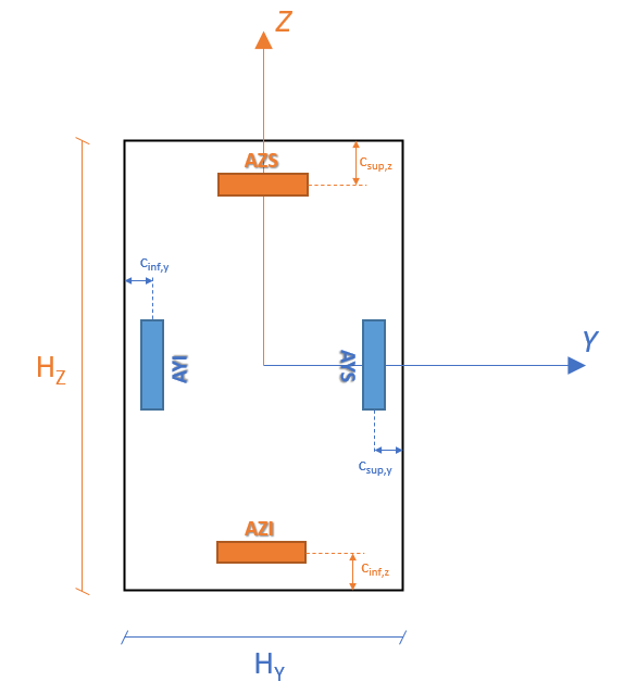
We consider a beam with a rectangular cross section, with dimensions \(h={H}_{Z}=\mathrm{0,3}m\) and \({b}_{w}={H}_{Y}=\mathrm{0,5}m\).
1.2. Material properties#
Not applicable to mechanical resolution (see § 1.3). See paragraph 1.3.2 for the parameters for determining the limit state for the material.
1.3. Boundary conditions and loads#
There is no mechanical resolution operator called in this test.
A generalized analytical field of effort is applied as input to the operator CALC_FERRAILLAGE, corresponding to one of the following configurations:
1.3.1. Case of loading at ELU#
compression force of \(1000000\text{N}\), and a shear force of \(100000\text{N}\) along the axis \(\text{Z}\)
traction force of \(1000000\text{N}\), and a shear force of \(-100000\text{N}\) along the axis \(\text{Z}\)
tensile force of \(1000000\text{N}\), a shear force of \(-100000\text{N}\) along the axis \(\text{Z}\) and a torsional moment of \(10000\text{Nm}\)
bending moment of \(100000\text{Nm}\) around the \(\text{Z}\) axis.
Bending moment of \(-100000\text{Nm}\) around the \(\text{Y}\) axis.
bending moment of \(-100000\text{Nm}\) around the \(\text{Z}\) axis and pull force of \(100000\text{N}\)
bending moment of \(-100000\text{Nm}\) around the \(\text{Y}\) axis and pull force of \(100000\text{N}\)
bending moment of \(-100000\text{Nm}\) around the \(\text{Z}\) axis and pull force of \(2000000\text{N}\)
bending moment of \(100000\text{Nm}\) around the \(\text{Z}\) axis and \(-150000\text{Nm}\) bending moment around the \(\text{Y}\) axis
bending moment of \(100000\text{Nm}\) around axis \(\text{Z}\), moment of bending of \(-150000\text{Nm}\) around axis \(\text{Y}\), and compression force of \(3000000\text{N}\)
bending moment of \(-150000\text{Nm}\) around the \(\text{Z}\) axis
bending moment of \(-260000\text{Nm}\) around the \(\text{Z}\) axis
bending moment of \(-380000\text{Nm}\) around the \(\text{Z}\) axis
compression force of \(4500000\text{N}\), bending moment of \(380000\text{Nm}\) around the axis \(\text{Z}\) and a shear force of \(100000\text{N}\) following \(\text{Z}\)
1.3.2. Load cases with the ELS Feature#
compression force of \(1000000\text{N}\), and a shear force of \(100000\text{N}\) along the axis \(\text{Z}\)
traction force of \(1000000\text{N}\), and a shear force of \(-100000\text{N}\) along the axis \(\text{Z}\)
tensile force of \(1000000\text{N}\), a shear force of \(-100000\text{N}\) along the axis \(\text{Z}\) and a torsional moment of \(10000\text{Nm}\)
bending moment of \(100000\text{Nm}\) around the \(\text{Z}\) axis.
Bending moment of \(-100000\text{Nm}\) around the \(\text{Y}\) axis.
bending moment of \(-100000\text{Nm}\) around the \(\text{Z}\) axis and pull force of \(100000\text{N}\)
bending moment of \(-100000\text{Nm}\) around the \(\text{Y}\) axis and pull force of \(100000\text{N}\)
bending moment of \(-100000\text{Nm}\) around the \(\text{Z}\) axis and pull force of \(2000000\text{N}\)
bending moment of \(100000\text{Nm}\) around the \(\text{Z}\) axis and \(-150000\text{Nm}\) bending moment around the \(\text{Y}\) axis
bending moment of \(100000\text{Nm}\) around axis \(\text{Z}\), moment of bending of \(-150000\text{Nm}\) around axis \(\text{Y}\), and compression force of \(3000000\text{N}\)
bending moment of \(-150000\text{Nm}\) around the \(\text{Z}\) axis
bending moment of \(-260000\text{Nm}\) around the \(\text{Z}\) axis
bending moment of \(-380000\text{Nm}\) around the \(\text{Z}\) axis
compression force of \(4500000\text{N}\), bending moment of \(380000\text{Nm}\) around the axis \(\text{Z}\) and a shear force of \(100000\text{N}\) following \(\text{Z}\)
1.3.3. Case of loading at the ELS Quasi-Permanent#
compression force of \(1000000\text{N}\), and a shear force of \(100000\text{N}\) along the axis \(\text{Z}\)
traction force of \(1000000\text{N}\), and a shear force of \(-100000\text{N}\) along the axis \(\text{Z}\)
tensile force of \(1000000\text{N}\), a shear force of \(-100000\text{N}\) along the axis \(\text{Z}\) and a torsional moment of \(10000\text{Nm}\)
bending moment of \(100000\text{Nm}\) around the \(\text{Z}\) axis.
Bending moment of \(-100000\text{Nm}\) around the \(\text{Y}\) axis.
bending moment of \(-100000\text{Nm}\) around the \(\text{Z}\) axis and pull force of \(100000\text{N}\)
bending moment of \(-100000\text{Nm}\) around the \(\text{Y}\) axis and pull force of \(100000\text{N}\)
bending moment of \(-100000\text{Nm}\) around the \(\text{Z}\) axis and pull force of \(2000000\text{N}\)
bending moment of \(100000\text{Nm}\) around the \(\text{Z}\) axis and \(-150000\text{Nm}\) bending moment around the \(\text{Y}\) axis
bending moment of \(100000\text{Nm}\) around axis \(\text{Z}\), moment of bending of \(-150000\text{Nm}\) around axis \(\text{Y}\), and compression force of \(3000000\text{N}\)
bending moment of \(-150000\text{Nm}\) around the \(\text{Z}\) axis
bending moment of \(-260000\text{Nm}\) around the \(\text{Z}\) axis
bending moment of \(-380000\text{Nm}\) around the \(\text{Z}\) axis
compression force of \(4500000\text{N}\), bending moment of \(380000\text{Nm}\) around the axis \(\text{Z}\) and a shear force of \(100000\text{N}\) following \(\text{Z}\)
1.4. Other calculation parameters#
1.4.1. Settings at ELU#
In ELU, we will consider 9 configurations on which we will start the calculation of the 14 load cases presented in §1.3.1:
Setup 1- Basic calculation:
calculation at EC2
upper csup coating, Y = csup, Z =4 cm
lower cinf coating, Y = cinf, Z = 4 cm
elastic limit of steel fyk= 500 MPa
Young’s modulus of Eys steel = 210,000 MPa
type diagram (sant-901) for steel = “B2”
characteristic strength of concrete fck= 35 MPa
density of the steel [s] = 7800 Kg/m3
αcc= 1.0/γc= 1.5/γs= 1.15
Configuration 2- Taking into account compression reinforcement:
calculation at EC2
FERR_COMP = “OUI “
upper csup coating, Y = csup, Z =4 cm
lower cinf coating, Y = cinf, Z = 4 cm
elastic limit of steel fyk= 500 MPa
Young’s modulus of Eys steel = 210,000 MPa
type diagram (sant-901) for steel = “B2”
characteristic strength of concrete fck= 35 MPa
density of the steel [s] = 7800 Kg/m3
αcc= 1.0/γc= 1.5/γs= 1.15
Configuration 3- Taking into account the impact of compression on the shear force resistance and the impact of shear force and torsion on the longitudinal reinforcement:
calculation at EC2
FERR_COMP = “OUI “
UTIL_COMPR = “OUI “
EPURE_CISA = “OUI “
upper csup coating, Y = csup, Z =4 cm
lower cinf coating, Y = cinf, Z = 4 cm
elastic limit of steel fyk= 500 MPa
Young’s modulus of Eys steel = 210,000 MPa
type diagram (sant-901) for steel = “B2”
characteristic strength of concrete fck= 35 MPa
density of the steel [s] = 7800 Kg/m3
αcc= 1.0/γc= 1.5/γs= 1.15
Configuration 4- Search for a symmetric sizing reinforcement:
calculation at EC2
FERR_COMP = “OUI “
FERR_SYME = “OUI “
SEUIL_SYME = 1 cm2
upper csup coating, Y = csup, Z =4 cm
lower cinf coating, Y = cinf, Z = 4 cm
elastic limit of steel fyk= 500 MPa
Young’s modulus of Eys steel = 210,000 MPa
type diagram (sant-901) for steel = “B2”
characteristic strength of concrete fck= 35 MPa
density of the steel [s] = 7800 Kg/m3
αcc= 1.0/γc= 1.5/γs= 1.15
Configuration 5- Sizing at BAEL91:
calculation at BAEL91
FERR_COMP = “OUI “
upper csup coating, Y = csup, Z =4 cm
lower cinf coating, Y = cinf, Z = 4 cm
elastic limit of steel Fe= 500 MPa
Young’s modulus of Eys steel = 210,000 MPa
type diagram (sant-901) for steel = “B2”
characteristic strength of concrete fcj= 35 MPa
density of the steel [s] = 7800 Kg/m3
αcc= 1.0/γc= 1.5/γs= 1.15
1.4.2. Parameters with the ELS Feature#
In ELS Characteristic, we will consider 4 configurations on which we will start the calculation of the 10 load cases presented in §1.3.2:
Setup 1- Basic calculation:
calculation at EC2
upper csup coating, Y = csup, Z =4 cm
lower cinf coating, Y = cinf, Z = 4 cm
characteristic strength of concrete fck= 35 MPa
authorized limit stress in steel: μs, lim = 400 MPa
maximum compressive stress authorized at the level of the underside of concrete:
►c, inf, lim = 21 MPa
maximum compressive stress authorized at the level of the underside of concrete:
►c, sup, lim=21 MPa
steel-concrete equivalence coefficient: αE = 15
density of the steel [s] = 7800 Kg/m3
Configuration 2- Taking into account compression reinforcement:
calculation at EC2
FERR_COMP = “OUI “
upper csup coating, Y = csup, Z =4 cm
lower cinf coating, Y = cinf, Z = 4 cm
characteristic strength of concrete fck= 35 MPa
authorized limit stress in steel: μs, lim = 400 MPa
maximum compressive stress authorized at the level of the underside of concrete:
►c, inf, lim = 21 MPa
maximum compressive stress authorized at the level of the underside of concrete:
►c, sup, lim=21 MPa
steel-concrete equivalence coefficient: αE = 15
density of the steel [s] = 7800 Kg/m3
Configuration 3- Search for a symmetric sizing reinforcement:
calculation at EC2
FERR_COMP = “OUI “
FERR_SYME = “OUI “
SEUIL_SYME = 5 cm2
upper csup coating, Y = csup, Z =4 cm
lower cinf coating, Y = cinf, Z = 4 cm
characteristic strength of concrete fck= 35 MPa
authorized limit stress in steel: μs, lim = 400 MPa
maximum compressive stress authorized at the level of the underside of concrete:
►c, inf, lim = 21 MPa
maximum compressive stress authorized at the level of the underside of concrete:
►c, sup, lim=21 MPa
steel-concrete equivalence coefficient: αE = 15
density of the steel [s] = 7800 Kg/m3
Setup 4- Calculation at BAEL91
calculation at BAEL91
FERR_COMP = “OUI “
upper csup coating, Y = csup, Z =4 cm
lower cinf coating, Y = cinf, Z = 4 cm
characteristic strength of concrete FCj= 35 MPa
authorized limit stress in steel: μs, lim = 400 MPa
maximum compressive stress authorized at the level of the underside of concrete:
S-C, INF, LIM = 21 MPa
maximum compressive stress authorized at the level of the underside of concrete:
S-C, SUP, LIM = 21 MPa
steel-concrete equivalence coefficient: N = 15
density of the steel [s] = 7800 Kg/m3
1.4.3. Settings at the ELS Quasi-Permanent#
At ELS Permanent4 configurations will be considered on which we will start the calculation of the 10 load cases presented in §1.3.3:
Setup 1- Basic calculation:
calculation at EC2
upper csup coating, Y = csup, Z =4 cm
lower cinf coating, Y = cinf, Z = 4 cm
characteristic strength of concrete fck= 35 MPa
elastic limit of steel: fyk = 500 MPa
Young’s modulus of steel: Eys = 210,000 MPa
maximum crack opening allowed on the underside: wmax, inf = 0.15 mm
maximum crack opening allowed on the upper side: wmax, sup = 0.15 mm
loading time coefficient: kt= 0.4
maximum compressive stress allowed in concrete for the control of non-linear creep: μc, lim, NL= 15.75 MPa
estimated diameter of the bars on the lower face along the X axis: Φ INF, X = 25 mm
estimated diameter of the bars on the upper face along the X axis: Φ SUP, X= 25 mm
estimated diameter of the bars on the lower face along the Y axis: Φ INF, Y= 25 mm
estimated diameter of the bars on the upper face along the Y axis: Φ SUP, Y= 25 mm
steel-concrete equivalence coefficient: αE = 15
density of the steel [s] = 7800 Kg/m3
Configuration 2- Taking into account compression reinforcement:
calculation at EC2
FERR_COMP = “OUI “
upper csup coating, Y = csup, Z =4 cm
lower cinf coating, Y = cinf, Z = 4 cm
characteristic strength of concrete fck= 35 MPa
elastic limit of steel: fyk = 500 MPa
Young’s modulus of steel: Eys = 210,000 MPa
maximum crack opening allowed on the underside: wmax, inf = 0.15 mm
maximum crack opening allowed on the upper side: wmax, sup = 0.15 mm
loading time coefficient: kt= 0.4
maximum compressive stress allowed in concrete for the control of non-linear creep: μc, lim, NL= 15.75 MPa
estimated diameter of the bars on the lower face along the X axis: Φ INF, X = 25 mm
estimated diameter of the bars on the upper face along the X axis: Φ SUP, X= 25 mm
estimated diameter of the bars on the lower face along the Y axis: Φ INF, Y= 25 mm
estimated diameter of the bars on the upper face along the Y axis: Φ SUP, Y= 25 mm
steel-concrete equivalence coefficient: αE = 15
density of the steel [s] = 7800 Kg/m3
Configuration 3- Search for a symmetric sizing reinforcement:
calculation at EC2
FERR_COMP = “OUI “
FERR_SYME = “OUI “
SEUIL_SYME = 5 cm2
upper csup coating, Y = csup, Z =4 cm
lower cinf coating, Y = cinf, Z = 4 cm
characteristic strength of concrete fck= 35 MPa
elastic limit of steel: fyk = 500 MPa
Young’s modulus of steel: Eys = 210,000 MPa
maximum crack opening allowed on the underside: wmax, inf = 0.15 mm
maximum crack opening allowed on the upper side: wmax, sup = 0.15 mm
loading time coefficient: kt= 0.4
maximum compressive stress allowed in concrete for the control of non-linear creep: μc, lim, NL= 15.75 MPa
estimated diameter of the bars on the lower face along the X axis: Φ INF, X = 25 mm
estimated diameter of the bars on the upper face along the X axis: Φ SUP, X= 25 mm
estimated diameter of the bars on the lower face along the Y axis: Φ INF, Y= 25 mm
estimated diameter of the bars on the upper face along the Y axis: Φ SUP, Y= 25 mm
steel-concrete equivalence coefficient: αE = 15
density of the steel [s] = 7800 Kg/m3
Setup 4- Calculation at BAEL91
calculation at BAEL91
FERR_COMP = “OUI “
upper csup coating, Y = csup, Z =4 cm
lower cinf coating, Y = cinf, Z = 4 cm
characteristic strength of concrete fck= 35 MPa
elastic limit of steel: fyk = 500 MPa
Young’s modulus of steel: Eys = 210,000 MPa
maximum crack opening allowed on the underside: wmax, inf = 0.15 mm
maximum crack opening allowed on the upper side: wmax, sup = 0.15 mm
loading time coefficient: kt= 0.4
maximum compressive stress allowed in concrete for the control of non-linear creep: μc, lim, NL= 15.75 MPa
estimated diameter of the bars on the lower face along the X axis: Φ INF, X = 25 mm
estimated diameter of the bars on the upper face along the X axis: Φ SUP, X= 25 mm
estimated diameter of the bars on the lower face along the Y axis: Φ INF, Y= 25 mm
estimated diameter of the bars on the upper face along the Y axis: Φ SUP, Y= 25 mm
steel-concrete equivalence coefficient: αE = 15
density of the steel [s] = 7800 Kg/m3