1. Reference problem#
1.1. Geometry#
The Aster‑MISS3D software uses the frequency coupling method to account for soil-structure interaction. This method, based on dynamic substructuring, consists in dividing the field of study into three sub-areas:
the ground,
the foundation,
the building.
The problem treated uses data from experiments conducted by NUPEC [bib2].
The floor
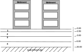
The ground corresponds to the profile with 5 horizontal layers shown in the figure below:

|
Figure 1.1-a: Configuration buildings juxtaposed [bib2]
Thickness (\(m\)) |
Young’s module (\(\mathit{MPa}\)) |
Density (\(\mathit{kg}\mathrm{/}{m}^{3}\)) |
Hysteretic damping (%) |
Poisson’s ratio |
||
1 |
0.50 |
97.78 |
97.78 |
1940 |
10 |
0.120 |
2 |
2.50 |
614.93 |
614.93 |
1940 |
10 |
0.371 |
3 |
3.00 |
1015.10 |
1015.10 |
1940 |
4 |
0.415 |
4 |
14.00 |
10190.00 |
10190.00 |
2210 |
4 |
0.386 |
5 (substratum) |
27.75 |
15015.00 |
15015.00 |
2210 |
4 |
0.343 |
Table 1.1-a: soil with buried foundation [bib2]
The foundation
The surface foundation of the two buildings is shown on [Figure 1.1-b] below. Two surface models of the foundation complete two skewer models of buildings ([Figure 1.1-c] below). To the initial surface model of 128 elements representing the base of the rigid double foundation, 64 surface elements whose thickness is the base of the foundations, i.e. 1.6 m, are added to represent the intermediate flexible connection foundation of variable stiffness parameterized by its Young’s modulus and embedded in the rigid double foundation [Figure 1.1-b]. The two surface configurations of a single building are juxtaposed, leaving a distance of \(8m\) between each floor slab.

Figure 1.1-b: Foundation surface models and meshes
The building
The building is modelled in 1D by a skewer model composed of 7 non-heavy beams of 5 types and 4 masses as shown in [Figure 1.1-c] below:

X=East-West
z
Y=North-South
Figure 1.1-c: Modeling each of the buildings
Building characteristics:
The characteristics of the beams and masses that were used to model each of the buildings are given in the tables below:
Mass |
Altitude |
Mass |
Mass inertia (\({10}^{3}{\mathit{kg.m}}^{2}\)) |
||
(\(m\)) |
(\({10}^{3}\mathit{kg}\)) |
\({J}_{\mathit{xx}}\) |
\({J}_{\mathit{yy}}\) |
\({J}_{\mathit{zz}}\) |
|
\(\mathit{M1}\) |
10.38 |
79.25 |
410.72 |
482.34 |
893.06 |
\(\mathit{M2}\) |
6.25 |
104.09 |
574.75 |
694.04 |
1268.79 |
\(\mathit{M3}\) |
4.8 |
156.71 |
1020.85 |
1071.22 |
2092.07 |
\(\mathit{M4}\) |
0.8 |
316.97 |
1846.7 |
1844.02 |
3690.72 |
Table 1.1-b: characteristics of the weights of the skewer model provided by NUPEC [bib2]
Beam |
Area (\({m}^{2}\)) |
Moment of inertia (\({m}^{4}\)) |
Shear coefficient |
Torsion constant (\({m}^{4}\)) |
||
\(A\) |
\({I}_{z}\) |
\({I}_{y}\) |
\({A}_{y}\) |
\({A}_{z}\) |
\({J}_{x}\) |
|
\(\mathit{P1}\) |
59.50 |
341.33 |
341.33 |
1/0.93 |
1/0.93 |
682.70 |
\(\mathit{P2}\) |
8.28 |
39.51 |
54.77 |
2.94 |
2.94 |
94.30 |
\(\mathit{P3}\) |
63.19 |
341.33 |
341.33 |
1/0.99 |
1/0.99 |
682.70 |
\(\mathit{P4}\) |
19.78 |
148.34 |
149.14 |
2.13 |
2.13 |
297.50 |
\(\mathit{P5}\) |
64.00 |
341.33 |
341.33 |
1.00 |
1.00 |
682.70 |
Table 1.1-c: characteristics of the beams of the brochette model provided by NUPEC [bib2]
The geometry taken into account in Code_Aster is that of the structure of buildings as well as their foundation. Geometric and physical ground data are directly given to MISS_3D.
1.2. Material properties#
The floor
The mechanical characteristics of the layers of the soil model that were used are those indicated in table 1.1-a.
The rigid double foundation and the building
E |
\(31000\mathit{MPa}\) |
NUDE |
\(0.16\) |
RHO |
|
ALPHA |
|
Module \(E\) of the flexible intermediate connection foundation is configured as a multiple of 10 of the building module with a multiplying factor between 0.001 and 1000.
1.3. Boundary conditions and mechanical loads#
Each of the 2 links between a 1D model and its foundation is achieved by a solid link condition between the foundation and the node common to the building model. This knot is blocked and a solid body movement is imposed on the raft. To calculate the constrained modes associated with the connection foundation, the degrees of freedom of translation of the connection foundation are also blocked.
The top of the building model is excited in the horizontal directions \(X\) and \(Y\) with a harmonic loading \(F\mathrm{=}{F}_{o}\mathrm{sin}\omega t\) whose force modulus \({F}_{o}\) is \(10\mathit{kN}\) with a pulsation that varies from \(0\) to \(20\mathit{Hz}\) in steps of \(\mathrm{0,1}\mathit{Hz}\). In Code_Aster, this is equivalent to imposing a loading type FORCE_NODALE and transmitting in IMPR_MISS_3D the corresponding assembled vector with a unit frequency multiplier function.
Excitation is applied as shown on [Figure 1.1-b].