1. Reference problem#
1.1. Geometry#
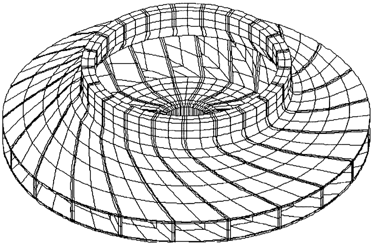
Figure 1.1-1: Problem geometry
An overview of the structure is shown in Figure 1.1: it has 21 sectors. The hub diameter is \(60\mathit{mm}\), the outer diameter is \(480\mathit{mm}\).
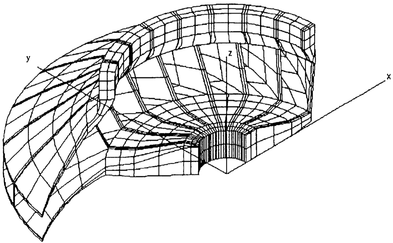
Figure 1.1-2: Detailed view of the geometry of the problem
Figure 1.2 shows a detailed view comprising 8 sectors. The axis system shown is structural system \(XYZ\). Each point can be identified in this system or, equivalently, in a system of cylindrical axes. The axis of revolution of the cylindrical coordinate system coincides with the \(Z\) axis and the azimuthal coordinate \(q\) has its origin in the plane \(XZ\).
The right and left borders of the sector are defined by the points which have, in the cylindrical coordinate system, an angular difference equal to the opening angle of the sector, i.e. \(1/{21}^{\mathit{ème}}\) of \(360°\). The points on both borders go in pairs: the minimum \(q\) angle point belongs to the right border, the maximum \(q\) point belongs to the left border.
1.2. Material properties#
Young’s module |
\(E=2.1\times {10}^{11}\mathit{Pa}\) |
Poisson’s Ratio |
\(\nu =0.3\) |
Density |
\(\rho =7800.0{\mathit{kg.m}}^{-3}\) |
1.3. Boundary conditions and loads#
Imposed displacement:
Wheel hub embedding |
\(\mathit{DX}=0\), \(\mathit{DY}=0\), \(\mathit{DZ}=0\) |
Imposed rotation:
Road |
\(\omega =2000{\text{rd.s}}^{-1}\) |