4. B modeling#
4.1. Characteristics of modeling and meshes#
Digital mesh:
The numerical mesh is identical to that used in the previous case. It is made with I‑DEAS Master Series 5 version and includes 2667 knots and 3328 \(\mathrm{3D}\) linear meshes. A group with a single node is added to serve as an interface.
Experimental mesh:
The measurement mesh includes only 5 point elements and 5 nodes positioned as shown in the following figure:
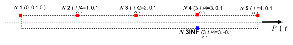
4.2. Characteristics of the measurements#
The experimental measurements provided are:
At nodes \(\mathrm{N3}\), \(\mathrm{N4}\), and \(\mathrm{N5}\):
The data is the axial stresses, applied in the \(x\) direction.
The time sampling is constant: the initial time is \(0s\), the time step is \({10}^{-5}s\), and the number of moments is 1001 (i.e. up to a final time of \(0.01s\)).
The values come from the direct calculation carried out with*Code_Aster*.
4.3. Characteristics of the modal base#
The modes are stored in a [modal_base] concept, containing the first two dynamic traction modes and the static mode at node \(\mathrm{N3INF}\) for the \(\mathrm{DX}\) degree of freedom. The interface is of the Craig-Bampton type. The base therefore contains a total of 3 modes.
Note:
Since the number of modes is very small, the solution depends on the modal base. However, the modes determined for this modeling are not the same as those of the modal reference base, and it is not possible to perform the direct calculation with Code_Aster on a concept [modal_basis]. Therefore, only the answers corresponding to the measurements provided can be validated. No comparison can be made on the other answers.
4.4. Tested sizes and results#
Identification |
Reference |
||
at*t* = 9. 10—4s |
3.416 10+7 |
||
SIXX |
At node \(\mathrm{N3}\) |
at*t* = 17. 10—4s |
8.046 10+7 |
\((\mathrm{Pa})\) |
at*t* = 25. 10—4s |
4.251 10+7 |
|
at*t* = 9. 10—4s |
4.650 10+7 |
||
SIXX |
At node \(\mathrm{N4}\) |
at*t* = 17. 10—4s |
6.671 10+7 |
\((\mathrm{Pa})\) |
at*t* = 25. 10—4s |
4.293 10+7 |
|