3. Modeling A#
3.1. Characteristics of modeling#
The characteristics used and the mesh are those deduced from the data in paragraph 1. Harmonic response and transfer functions have been calculated for reduced frequencies \(>\) (where \(>\)). The results obtained by Mita and Luco for these reduced frequencies are presented in the reference [bib2].
3.2. Characteristics of the mesh#
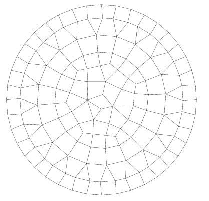
The circular foundation mesh is shown below (see §1.1):
3.3. Tested sizes and results#
For the case with spatial variability, we choose \(>\) and we test against the results of the literature (SOURCE_EXTERNE) with a tolerance of \(>\).
Results achieved with DYNA_ISS_VARIpour \(>\) and:
\(>\) |
|
|
1.0 |
0.767 |
0.767 |
2.0 |
0.437 |
0.437 |
3.0 |
0.251 |
0.251 |
As a reminder, the reference results [bib2], see also §2.2:
\(>\) |
|
|
1.0 |
0.732 |
0.730 |
2.0 |
0.402 |
0.416 |
3.0 |
0.251 |
0.270 |
In addition, a NON_REGESSION test is done for the values calculated by DYNA_ISS_VARI with a tolerance of \(>\) (by default value).
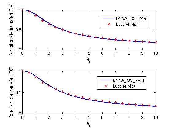
Comparison of transfer functions \(>\) obtained with DYNA_ISS_VARI and with Mita and Luco:
For case \(>\), we test the response after projection onto physical coordinates. Since the foundation is rigid and massless, all the nodes undergo the same displacement which is equal to 1.0 in direction \(>\) for an excitation in direction \(>\).
\(>\)
\(>\) is the modal impedance matrix, \(>\) the modal response and \(>\) for a seismic excitation in the \(>\) direction and \(>\) for a vertical earthquake.
\(>\) |
|
|
1.0, 2.0 3.0 |
1.0 1.0 1.0 |
1.0 1.0 1.0 |
With a via REST_SPEC_PHYS projection, we get the result:
\(>\) |
|
SPEC N11 “DZ” |
1.0 |
1.00527E+00 |
1.03014E+00 |
A test of type ANALYTIQUE is carried out with a tolerance of \(>\) for “DX” and \(>\) for “DZ”.