4. B modeling#
4.1. Characteristics of modeling#
We use a POU_D_T model.
4.2. Characteristics of the mesh#
The mesh contains 20 elements of type SEG2.
4.3. Tested sizes and results#
The first 6 natural frequencies of the embedded beam are tested.
We test the movement of the center of the beam in the direction of the earthquake at various times.
We test the value of the equivalent moment calculated by POST_RCCM for a mesh/node pair using a AUTRE_ASTER reference obtained using the functionalities of the command CALC_TABLE.
4.4. notes#
In the following figure (), the evolution of the displacement of the center of the beam is plotted by the calculation on a physical basis and the by calculation on a modal basis. It should be noted that these two movements are not comparable in the sense that the calculation on a physical basis gives a relative displacement that is difficult to interpret in the multi-support case: the concept of training displacement is no longer trivial for multi-support calculation. It is therefore not possible to compare the two results, nor to draw conclusions from them.
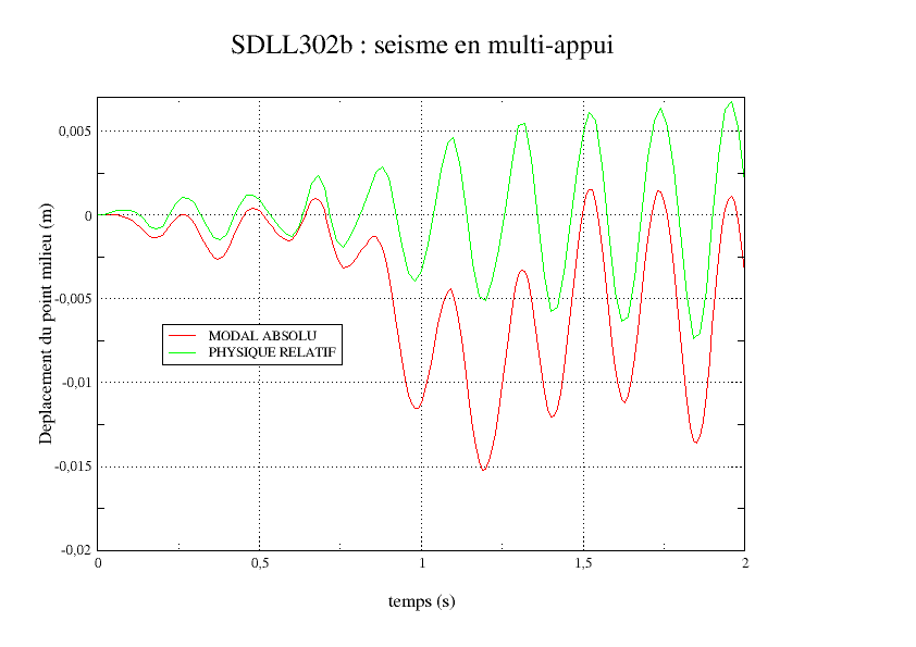
Illustration 3: SDLL302b: transverse displacement in the middle of the beam in multi-support design.
It should also be noted that, in contrast to modeling A, the displacement calculated on a modal basis appears to be very smooth (in accordance with the « physical sense » of the engineer). This is simply due to the fact that in modeling B, we left the option by default (method TRAPEZE) to integrate the accelerogram. However, it is recommended because it does not create artificial oscillations such as those produced by method SIMPSON).