1. Reference problem#
1.1. Geometry#
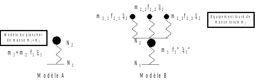
Model A, representing the flexure mode of a floor taking into account heavy equipment, is modelled.
1.2. Model properties#
The floor has the following properties:
mass \({m}_{1}\mathrm{=}1\),
vertical stiffness \({k}_{1}\mathrm{=}4000\),
amortization \({\xi }_{1}\mathrm{=}0.07\).
The natural frequency of the floor is \({f}_{1}^{\mathrm{\ast }}\mathrm{=}10.07\).
The equipment has the following properties:
mass \({m}_{2\mathrm{-}1}\mathrm{=}0.05\) \({m}_{2\mathrm{-}2}\mathrm{=}0.025\) \({m}_{2\mathrm{-}3}\mathrm{=}0.025\),
vertical stiffness \({k}_{2\mathrm{-}1}\mathrm{=}200\) \({k}_{2\mathrm{-}2}\mathrm{=}800\) \({k}_{2\mathrm{-}3}\mathrm{=}50\),
amortization \({\xi }_{2}\mathrm{=}0.05\).
The natural frequencies of each equipment are: \({f}_{2\mathrm{-}1}\mathrm{=}10.07\), \({f}_{2\mathrm{-}2}\mathrm{=}28.47\) and \({f}_{2\mathrm{-}3}\mathrm{=}7.12\).
In the case studied, the mass ratio is \(\lambda \mathrm{=}\frac{{m}_{2}}{{m}_{1}}\mathrm{=}0.1\). Since the frequency of an equipment is identical to that of the support, we are in a case where the interaction is maximum.
1.3. Boundary conditions and loads#
Boundary conditions: Node N1 is blocked.
Loading: a sinusoidal acceleration is imposed on the mass-spring system \(f(t)=\mathrm{sin}(2\mathrm{\pi }20t)\)
The transient response of the system is calculated with the operator DYNA_VIBRA on a physical basis (BASE_CALCUL =” PHYS “) in transient (TYPE_CALCUL =” TRAN”), with a time step of 0.1 ms.