5. D modeling#
This modeling provides a reference for test EPX bm_str_lcab_frot_amor which reproduces the tension of a friction cable. The reference values are the voltage profiles calculated with DEFI_CABLE_BP.
Test EPX bm_str_lcab_frot_amor uses EPX damping.
It uses both LIRE_EUROPLEXUS without going through CALC_EUROPLEXUS to retrieve the result of the test EPX contained in a file MED (given in unit 19) and reproduces the calculation with CALC_EUROPLEXUS.
5.1. Friction material#
The material BPEL_ACIER is assigned to the cable for Code_Aster and to the friction discretes for EPX with the following parameters:
FROT_LINE |
0.003 |
FROT_COURB |
0.2 |
5.2. Boundary conditions and loads#
EPX :
Same boundary conditions and loading as modeling A. Only the multiplier function changes to simulate anchor recoil.
Time |
Coefficient |
0.0 |
|
0.002 |
1.0 |
0.06 |
1.0 |
0.1 |
0.933333 |
1.0 |
1.0 |
The change in the multiplier function to 0.933333 corresponds to a 0.2 m retreat from ANCR2.
Aster_code:
Same boundary conditions as modeling B. Prestress loading differs only on the initial tension value given by TENSION_INIT. Here it is equal to \(315367000\). The call to DEFI_CABLE_BP is made twice, once without anchor recoil and a second time with an anchor recoil of 0.116.
The voltage value to be applied in Code_Aster was determined in the following manner. The results of calculation EPX have been retrieved. Field EPX of cable constraints has been transformed into force fields. From this field at the Gauss points (SIEF_ELGA) we calculated the field at the corresponding nodes (SIEF_NOEU). The first cable node from node ANCR2 whose updated Y coordinate did not exceed -2 m was then detected in the displacement field at time 0.06s. Physically, it is the first cable node that did not come out of the concrete during this tension phase. The voltage value to be applied in Code_Aster is the value of the effort field to the nodes at this node.
Contrary to what one might think, the anchor setback to be applied in Code_Aster is not 0.2m but 0.116m. In fact, the anchor setback should not be calculated from node ANCR2 but from the last node still included in the concrete after the initial phase. The value of 0.116m is then obtained.
5.3. Comparison of voltage profiles#
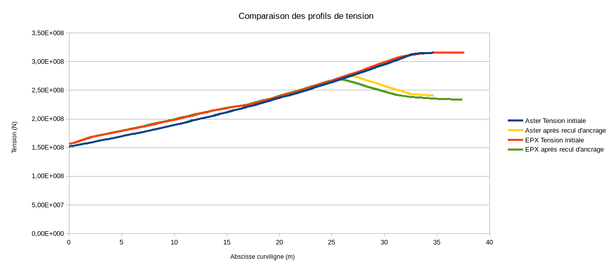
One gives here the analysis made in document EPX:
In the initial tension phase, we see that the curves are superimposed almost perfectly for curvilinear abscissa greater than about 20.0 m. By printing the value of the curvatures at each node calculated in EPX, we noticed that some values in the middle of the cable were quite different from the others, while in the circular part the curvature must be the same at each point. This is probably due to very slight inaccuracies in the mesh at this level. Code_Aster does not see it because it uses a spline method that interpolates the cable path globally while in EPX we simply interpolate the path locally.
Regarding the anchor recoil, we have slightly larger differences but the curves are parallel on this part. The differences may come from taking into account the friction on nodes that are normally out of concrete or from the interpretation of the reference node to determine the anchor recoil to be applied in Code_Aster.
5.4. Tested sizes and results#
We test the maximum difference between the Code_Aster and EPX tension profiles at the end of the initial tension and anchoring recoil phases.
Moment |
Maximum Gap |
0.06 |
0.0447086123078 |
0.12 |
0.0605346658829 |