1. Modeling A#
1.1. Geometry#
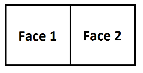
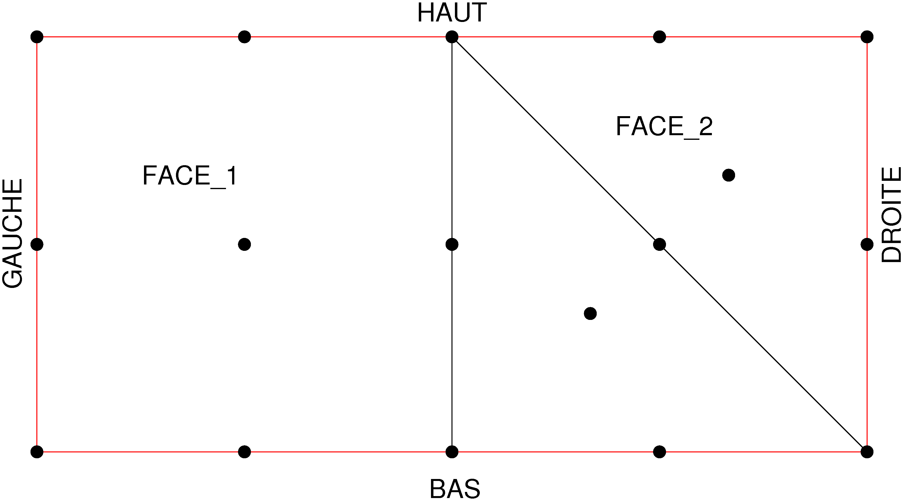
The geometry, shown in the following figure, is composed of two squares with side \(1m\).
1.2. Characteristics of the mesh#
The mesh is 2D, quadratic, and is shown in the following figure:
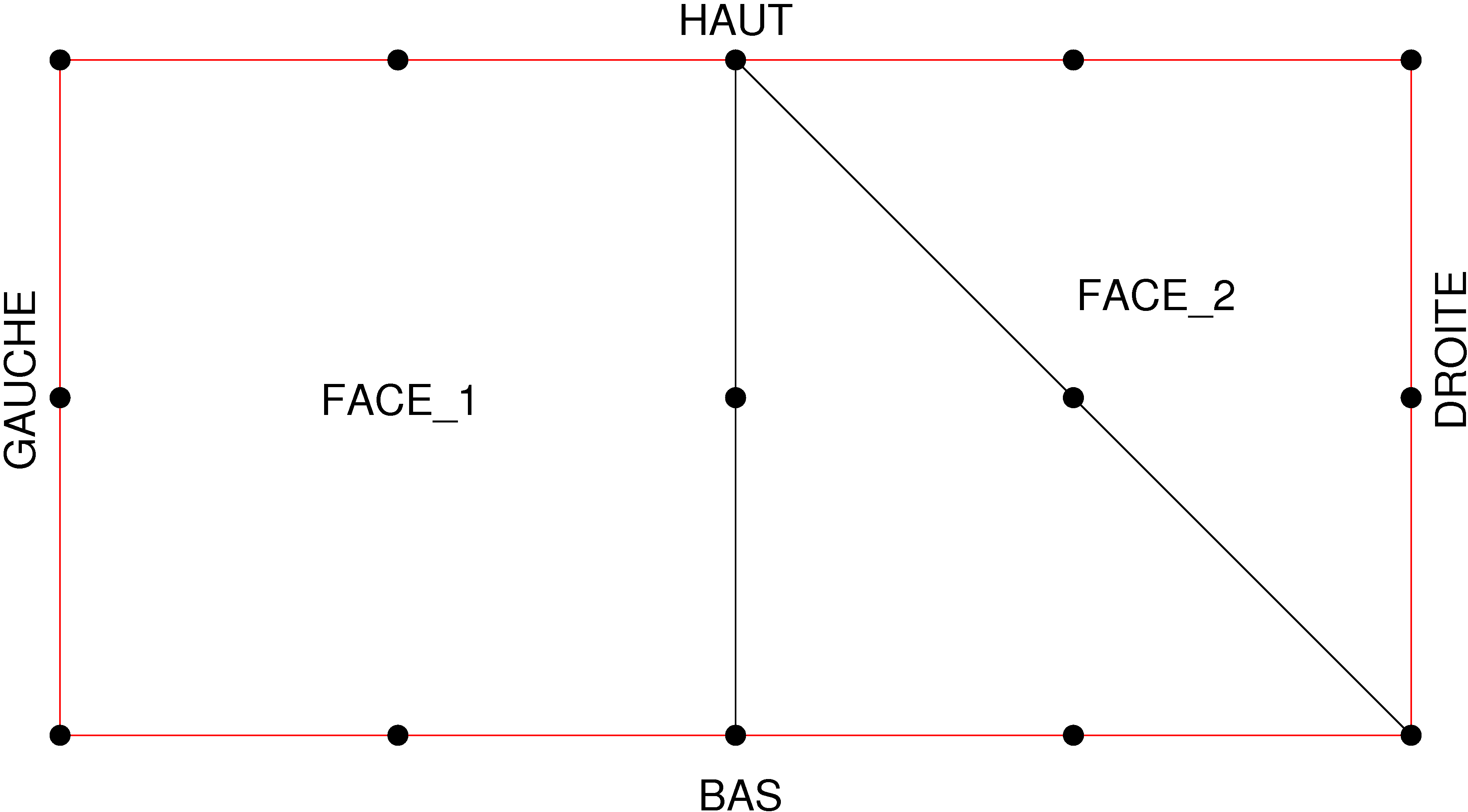
It is composed of 14 knots for a QUAD8 stitch making up group FACE_1 and two TRIA6 stitches making up group FACE_2. The edge segments are present in the form of SEG3 meshes and are arranged in groups BAS, HAUT, DROITE, GAUCHE.
1.3. Adaptations made and resulting meshes#
1.3.1. First series of adaptations#
Two refinements are carried out using the initial mesh and a field of internal variables, with a proportion of meshes to be refined of 50%. For the first component of the field, \(\mathit{V1}\), the value \(\mathrm{-}1\) is assigned to the nodes on face 1 and the value \(\mathrm{-}2\) is assigned to the nodes on face 2. The keyword USAGE_CMP is equal to RELATIF for the first adaptation and ABSOLU for the second. The aim is to compare the results of the two options. We therefore expect to refine side 1 to the first adaptation and side 2 to the second. To test it, we will use the field created by MACR_ADAP_MAIL with the option ADD_CHAM =( _F (CHAM_CAT =” DIAMETRE “),). This field contains the value of the diameter of each mesh after refinement. For triangles resulting from refinement by conformity, this is the length of the longest side whose value is \(\sqrt{1+\frac{1}{{2}^{2}}}\mathrm{=}\mathrm{1,118033989}\). For the quadrangles resulting from the refinement, this is the diagonal whose value is \(\sqrt{\frac{1}{{2}^{2}}+\frac{1}{{2}^{2}}}\mathrm{=}\mathrm{0,70710681}\). For triangles resulting from standard refinement, the diameter is their largest side, \(\mathrm{0,70710681}\).
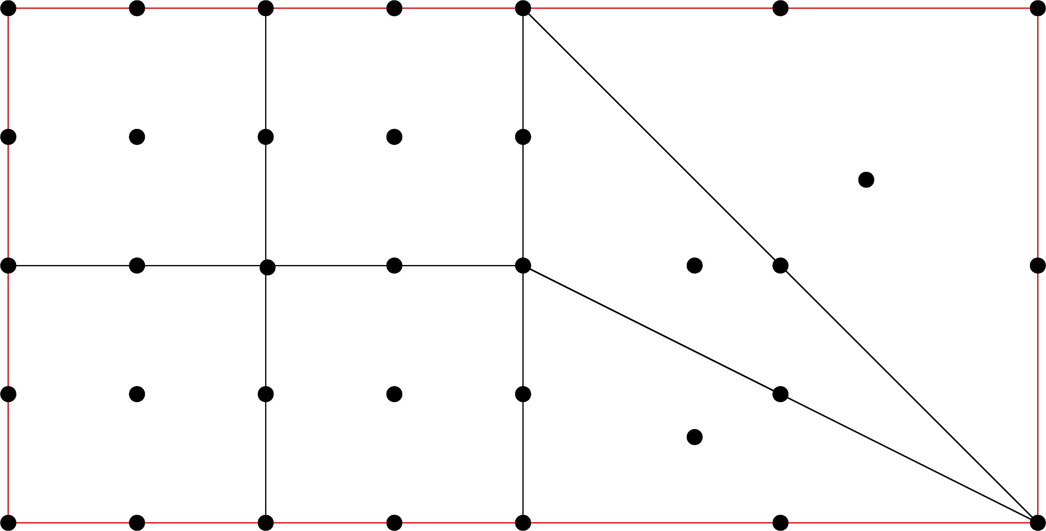
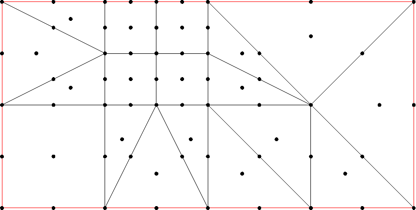
The following figure shows the adapted mesh with USAGE_CMP = RELATIF:
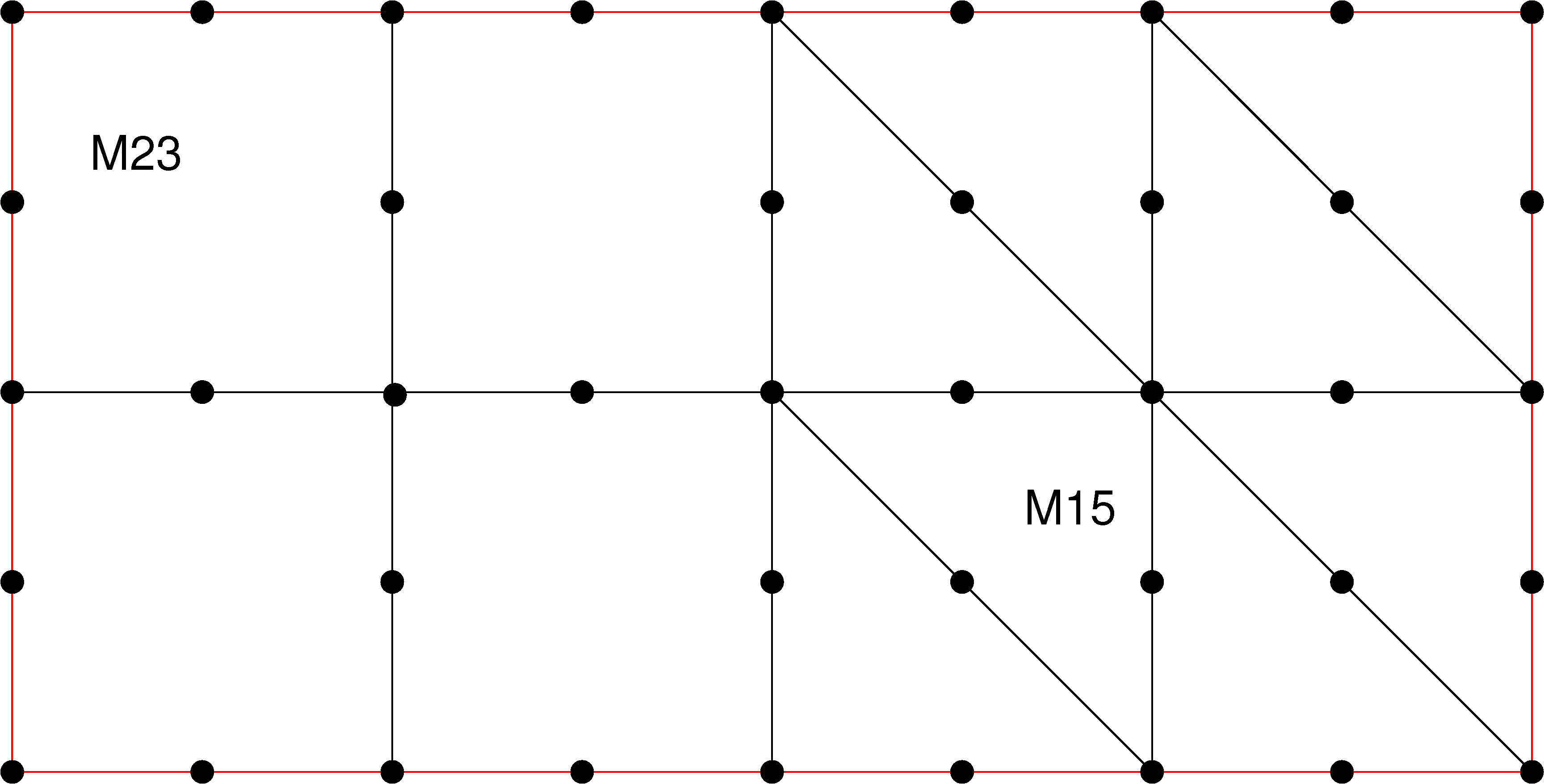
In accordance with our expectations, the No. 1 side is undergoing refinement.
Note:
Validation, based on the diameter value, will be carried out on cells 15 and 23.
The following figure shows the adapted mesh with USAGE_CMP = ABSOLU:
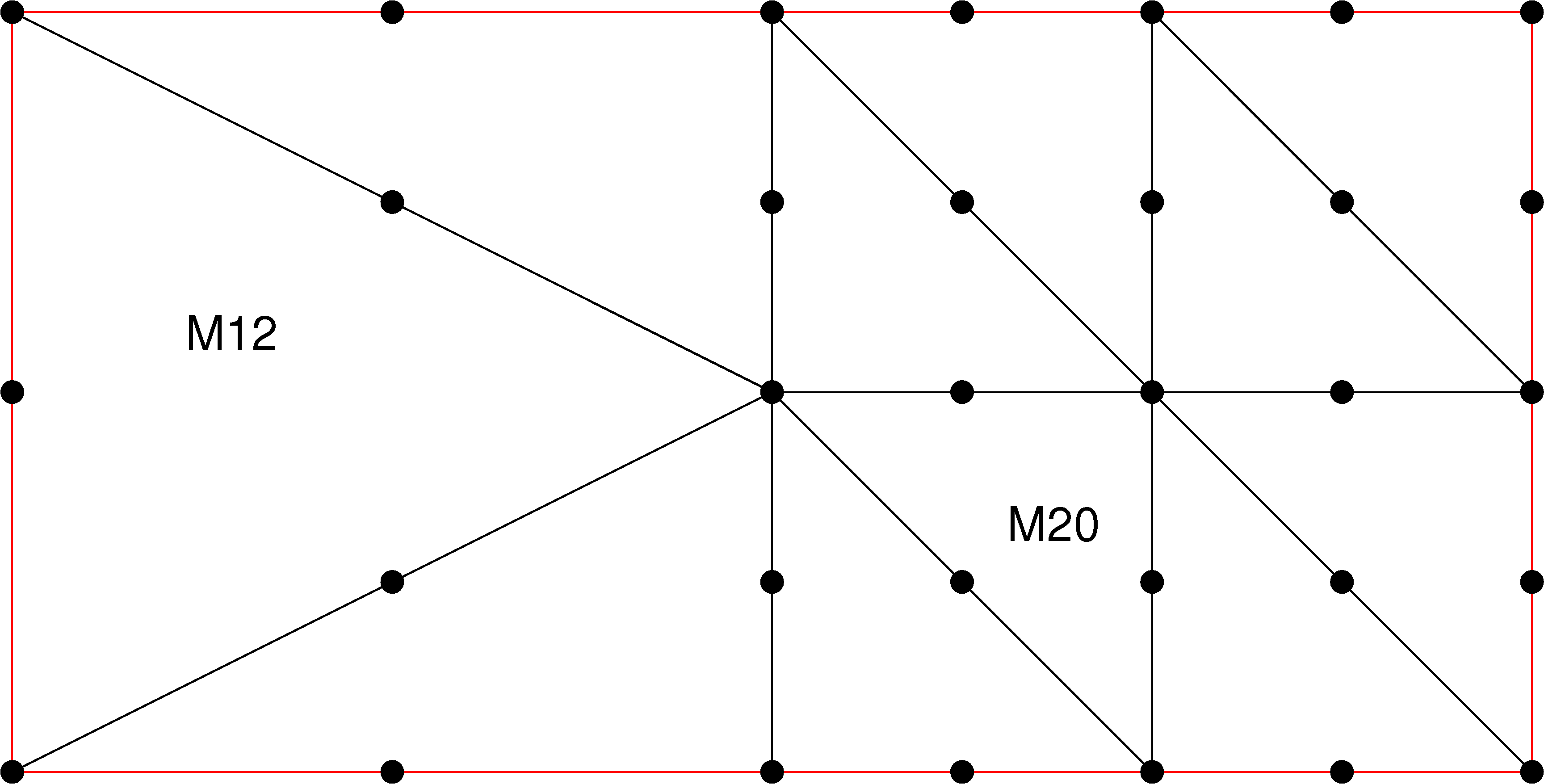
In accordance with our expectations, side No. 2 is undergoing refinement.
Note:
Validation, based on the diameter value, will be carried out on cells 12 and 20
1.3.2. Second series of adaptations#
Two cycles of uniform refinement - deraffination are carried out from the initial mesh. This time, the output mesh of adaptation \(n\) is used as the input mesh of adaptation \(n+1\). For refinements, a resulting field corresponding to the number of refinements per mesh is created using the keywords ADD_CHAM =( _F (CHAM_CAT =” NIVEAU “,),). For deraffinations, this field is used as a criterion with the option NIVE_MIN =1. We try to verify that we are not going to de-refine at the end of the first cycle and that we are going to de-refine at the end of the second.
The adapted mesh, after the first cycle, is shown in the following figure:
Refinement has taken place while deraffination has not been achieved.
Note:
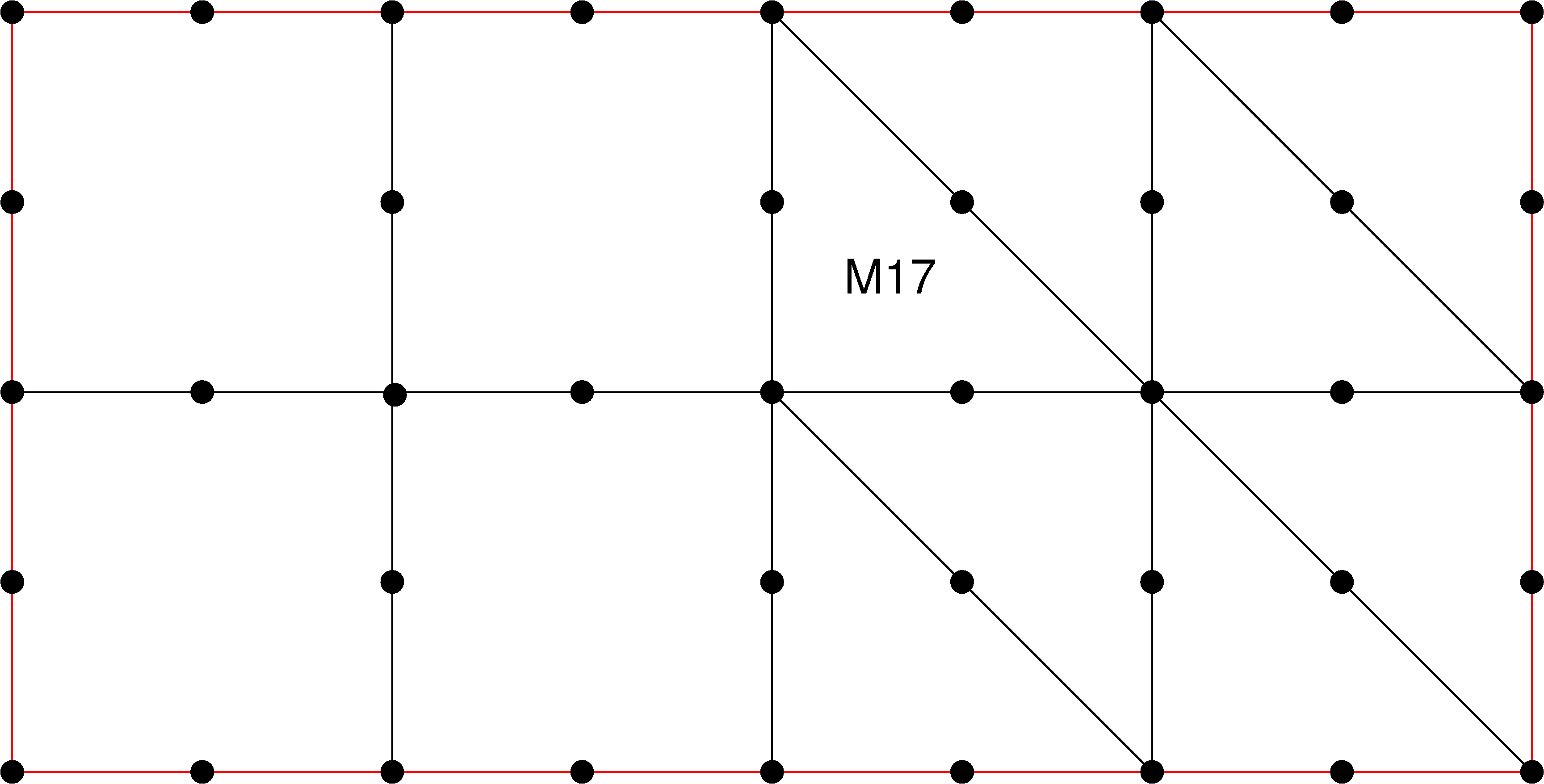
The validation, from the “NIVEAU” field, will be carried out on mesh 17. At the end of the first cycle, as the deraffination has not been completed, the value of this field must be equal to 1.
The adapted mesh, after the second refinement, is shown in the following figure:
The new refinement has been successfully achieved.
Note:
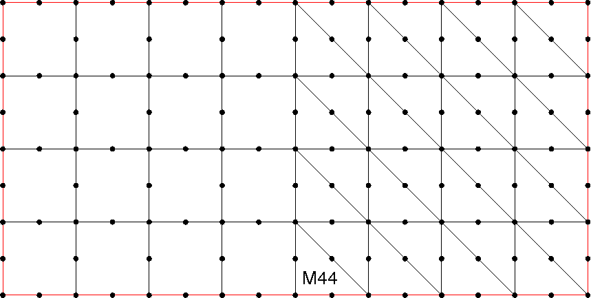
Validation, starting from the “NIVEAU” field, will be carried out on mesh 44. At the end of the refinement of the second cycle the value of this field must be equal to 2.
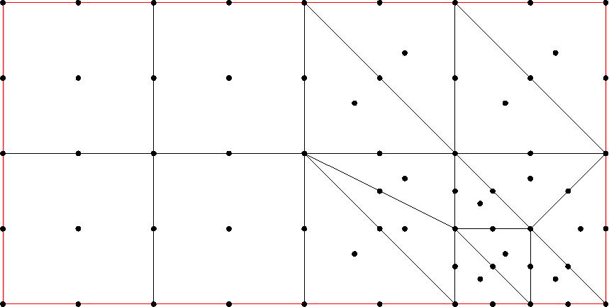
The adapted mesh, after the second cycle, is shown in the following figure:
The de-refinement of the second cycle has therefore been successfully completed.
Note:
The validation, from the “NIVEAU” field, will be carried out on mesh 17. At the end of the second cycle as the de-refinement worked, the value of this field should be equal to 1 again.
1.3.3. Third series of adaptations#
The mesh is enriched to contain TRIA7 and QUAD9 meshes. It is shown by the following figure:
Mesh No. 1 is obtained by requesting the refinement of the meshes in group FACE_1.
Mesh No. 2 is obtained by refining the meshes, one edge of which is included in the pierced disk with a center \((\mathrm{0,75}\mathrm{/}\mathrm{0,75})\), an inner radius \(\mathrm{0,1}\), and an outer radius \(\mathrm{0,4}\).
The mesh No. 3 is obtained by deraffinating the meshes contained in the rectangle of corners \((\mathrm{0,5}\mathrm{/}\mathrm{0,5})\) and \((1\mathrm{/}1)\) and by refining the meshes whose edge is included in the rectangle of corners \((\mathrm{1,5}\mathrm{/}0)\) and \((2\mathrm{/}\mathrm{0,5})\).
The tests are done on the centers of inertia of each FACE_1 and FACE_2 half of the structure.
1.4. Tested sizes#
The following quantities of the first two refinements are tested:
The following quantities of the two cycles of uniform refinement - deraffination are tested:
Analytical Values |
Tolerance |
|
(End of cycle 1) Level of mesh 17 |
1.E-6 |
|
(Refinement of cycle 2) Level of mesh 44 |
1.E-6 |
|
(End of cycle 2) Mesh Level 17 |
1.E-6 |
The following quantities of the three refinement - deraffination cycles are tested:
Non-regression values |
Tolerance |
|
Face No. 1 |
1.283333333 |
1.E-6 |
Face No. 2 |
1.383333333 |
1.E-6 |