1. Reference problem#
1.1. Geometries used for A, B, C models#
Several geometries are used to test the various combinations.
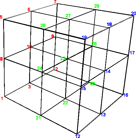
Figure 1.1-a : Geometry with 8 volume meshes HEXA8 .
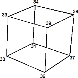
Figure 1.1-b: Geometry with 1 volume mesh of type HEXA8.
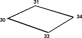
Figure 1.1-c: Geometry with 1 surface mesh of type QUAD4.
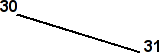
Figure 1.1-d: Geometry with 1 line mesh of type SEG2.
Dimensions:
Volume meshes have \(1.0m\) edges.
Surface meshes have \(1.0m\) edges.
The line mesh has a length of \(1.0m\).
1.2. Geometries used for D, E, F models#
Several geometries are used to test the various combinations.
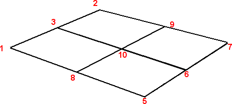
Figure 1.2-a: Geometry with 4 surface meshes of type QUAD4.
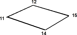
Figure 1.2-b: Geometry with 1 surface mesh of type QUAD4.
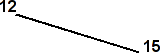
Figure 1.2-c: Geometry with 1 line mesh of type SEG2.
Dimensions:
Surface meshes have \(1.0m\) edges.
The line mesh has a length of \(1.0m\).
1.3. Material properties#
Not applicable.
1.4. Boundary conditions and loads#
For models A, B, C the nodes 1, 3, 2, 2, 8, 8, 8, 8, 8, 8, 8, 10, 10, 10, 9, 9, 5, 6, 7 are translationally locked in the directions \(X\), \(Y\), \(Z\). A non-zero displacement is imposed on nodes 12, 13, 16, 16, 16, 15, 15, 15, 15, 15, 14, 17, 19, 18, 20 in the directions \(X\), \(Y\), \(Z\).
For the d, e, f models the nodes 1, 3, 2 are blocked in translation and in rotation in the directions \(X\), \(Y\), \(Z\). A non-zero displacement is imposed on nodes 5, 6, 7.
1.5. Initial conditions#
Not applicable for static analysis.