1. Reference problem#
1.1. Geometry and meshing#
We consider a rectangular plate with a side L=12 m and a height H=3 m. The thickness is B=0.3 m. The mesh is set, each element is square with a side of 0.3 m. We test the geometry in the Figure but also the same geometry that has undergone a rotation of 150°.
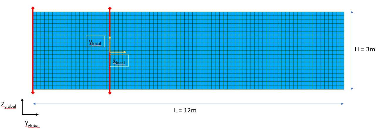
Figure 1.1-1: Geometry and mesh of the tested plate.
1.2. Cuts made#
Three cuts are made:
The first at the level of integration and is expressed in the global coordinate system.
The second is 3 m to the right of the boundary condition and is expressed in the global coordinate system.
The third is identical to the first but is expressed in the local coordinate system as described in the figure above.
The torsors are evaluated at the level of the middle of the cut.
1.3. Material properties#
The plate is made of concrete, characterized by the following elastic properties:
Young’s modulus: 30 GPa
Poisson’s ratio: 0.2
The calculation is linear elastic.
1.4. Modelizations#
CALC_COUPURE applies to plate elements. We will use modeling of type DKT (modeling A) and type DST (modeling B).
1.5. Boundary conditions and loads#
The plate is loaded statically or dynamically (spectral method) according to the modeling.
1.5.1. Static loads#
The plate is embedded on the left side.
Two loads are tested:
CH1: shear on the right side in the plane of the plate and normal force. Both are applied as forces distributed on the right side of the plate.
CH2: out-of-plane shear applied as a distributed load on the right side of the plate.
The forces applied are as follows:
\({F}_{X}=100\mathit{kN}\)
\({F}_{Y}=6000\mathit{kN}\)
\({F}_{Z}=600\mathit{kN}\)
1.5.2. Dynamic loads#
The plate is simply supported on the left and right sides.
A constant response spectrum is provided with reduced frequency and damping.
The acceleration spectrum is equal to 5000 mm/s in the x direction.
1.6. Reference quantities and results#
We test the quantities extracted by the command CALC_COUPURE for the 3 cuts made. The tests are analytical.
1.6.1. Static loads#
If we represent the plate as a beam embedded at its end, it is simple to calculate the internal forces in the static case.
We will look at the results at distance \(d\) from the embedment, for a cut parallel to the right and left sides. In the case where the torsor is expressed in the global coordinate system, the analytical results are:
CH 1:
\({R}_{1}=0\)
\({R}_{2}={F}_{Y}\)
\({R}_{3}={F}_{Z}\)
\({M}_{1}={F}_{Z}(L-d)\)
\({M}_{2}={M}_{3}=0\)
CH 2:
\({R}_{1}={F}_{X}\)
\({R}_{2}={R}_{3}={M}_{1}={M}_{2}={M}_{3}=0\)
In the local coordinate system, the results are:
CH 1:
\({R}_{1}={F}_{Y}\)
\({R}_{2}={F}_{Z}\)
\({R}_{3}=0\)
\({M}_{1}={M}_{2}=0\)
\({M}_{3}={F}_{Z}(L-d)\)
CH 2:
\({R}_{3}={F}_{X}\)
\({R}_{1}={R}_{2}={M}_{1}={M}_{2}={M}_{3}=0\)
1.6.2. Dynamic loads#
The acceleration response spectrum refers to an earthquake in the X direction, normal to the plane of the plate, which is therefore subjected to out-of-plane bending and shear stress.
The objective of the tests carried out is to verify the correct functioning of the modal combinations. Several configurations are studied:
Calculation of the torsor linked to the modal contribution of the first mode,
Torsor calculation taking into account the contribution of the first 2 modes (combination CQC).
Signature of the contribution of the first modal on unit acceleration.
Calculation of the quadratic combination of the contribution of the 3 earthquake directions,
Calculation of Newmark combinations linked to the 3 earthquake directions.