7. Neumann type loads#
7.1. Keyword FORCE_NODALE#
FORCE_NODALE = _F (
           ◆/GROUP_NO = grno,
           ◆ | FX = float or function,
             | FY = float or function,
             | FZ = float or function,
             | MX = float or function,
             | MY = float or function,
             | MZ = float or function,
           ◇ ANGL_NAUT = float,
)
The keyword factor FORCE_NODALE can be used to apply, to nodes or groups of nodes, nodal forces, defined component by component in the global coordinate system or in an obliqu coordinate system defined by three nautical angles. In all seriousness, the application of nodal loading is physically incorrect and can cause stress concentrations. It is best to use distributed loads.
Topological assignment:
◆ GROUP_NO
The load is affected on the nodes.
Components:
◆ FX, FY, FZ, MX, MY, MZ
Values of the components of the nodal forces of the nodal moments applied to the specified nodes. These nodal forces will be superimposed on the nodal forces resulting, possibly, from other loads. In axisymmetry, the values correspond to a sector of one radian (divide the real loading by \(2\pi\)).
◇ ANGL_NAUT
List of the three angles, in degrees, that define the oblique coordinate system for applying nodal forces (the last angles in the list can be omitted if they are zero). Nautical angles allow you to pass from the global coordinate system for defining the coordinates of the mesh to any oblique coordinate system (see § 3.9.3). By default the angles are identically zero and therefore the force components are defined in the global coordinate system.
7.2. Keyword FORCE_ARETE#
FORCE_ARETE = _F (
           ◇ GROUP_MA = Grma,
           ◆ | FX = float or function,
             | FY = float or function,
             | FZ = float or function,
             | MX = float or function,
             | MY = float or function,
             | MZ = float or function,
)
The keyword factor FORCE_ARETE can be used to apply line forces to an edge of a volume element or shell, defined component by component in the global coordinate system. This edge is defined by one or more cells or groups of cells of the segment type.
Topological assignment:
◇ GROUP_MA
The load is affected on the meshes, which are necessarily segments.
Components:
◆ FX, FY, FZ, MX, MY, MZ
Values of the components of the linear forces and moments applied to the specified cells. This load applies to the following models: DKT, DST, Q4G, 3D, and COQUE_3D.
7.3. Keyword FORCE_CONTOUR#
FORCE_CONTOUR = _F (
           ◇ GROUP_MA = Grma,
           ◆ | FX = float or function,
             | FY = float or function,
             | FZ = float or function,
),
The keyword factor FORCE_CONTOUR can be used to apply line forces to the edge of a 2D domain, defined component by component in the global coordinate system. This contour is defined by one or more cells of the segment type.
Note: basically it is a linear force but the unit is a surface force because we reason for a unit thickness (plane stresses, plane deformations) or divided by \(2\pi\) for axisymmetric models (see § 3.5).
Topological assignment:
◆ GROUP_MA
The load is affected on the meshes, which are necessarily segments.
Components:
◆ FX, FY, FZ
Values of the components of the linear forces applied to the specified cells. This load applies to the following models: D_PLAN, AXISet,, AXIS_FOURIER, including XFEM.
7.4. Keyword FORCE_FACE#
FORCE_FACE = _F (
           ◇ GROUP_MA = Grma,
           ◆ | FX = float or function,
             | FY = float or function,
             | FZ = float or function,
)
The keyword factor FORCE_FACE can be used to apply surface forces (therefore of the dimension of a pressure) on a 3D element face, defined component by component in the global coordinate system. This face is defined by one or more triangle or quadrangle meshes.
Topological assignment:
◆ GROUP_MA
The load is affected on cells that are necessarily triangles or quadrangles.
Components:
◆ FX, FY, FZ
Values of the components of the surface forces applied to the specified meshes. This load applies to the following models: 3D, 3D_HHM, 3D_HM,, 3D_THHM, 3D_THM, 3D_HH2, 3D_THH2M, and XFEM.
7.5. Keyword FORCE_INTERNE#
FORCE_INTERNE = _F (
           ◆/TOUT = "OUI" (or not specified),
             /GROUP_MA = grma,
           ◆ | FX = float or function,
             | FY = float or function,
             | FZ = float or function,
)
The keyword factor FORCE_INTERNE can be used in two cases:
To apply**volume**forces on a**3D domain**, defined component by component in the**global**coordinate system. This domain is defined by one or more cells such as**hexahedr**,**tetrahedr**,**pyramid**or**pentahedr**.
To apply**volume**forces on a**2D domain**, defined component by component in the**global**coordinate system. This domain is defined by one or more cells of the**triangle**or**quadrangle** type.
Topological assignment:
◆ TOUT, GROUP_MA
Components:
The load is affected on cells that are necessarily triangles or quadrangles in 2D and hexahedra, tetrahedra, pyramids or pentahedra in 3D.
◆ FX, FY, FZ
Values of the components of the volume forces applied to the specified cells.
For the 3D case, this load applies to the following models: 3D, 3D_SI, 3D_INCO,, 3D_HHMD,,,, 3D_HMD,, 3D_THHD, 3D_THHMD, 3D_THMD, 3D_THHM,, 3D_THM, 3D_HM,,, 888. 3D_THH 3D_HHM
For the 2D case, this load applies to the following models: C_PLAN, D_PLAN, AXIS,,, AXIS_FOURIER, AXIS_SI, AXIS_INCO, AXIS_THHM, AXIS_HM, AXIS_THH, AXIS_HHM, AXIS_THM D_PLAN_THHM D_PLAN_HM, D_PLAN_THH, D_PLAN_HHM, D_PLAN_THM.
7.6. Keyword PRES_REP#
PRES_REP = _F (
           ◆ | ALL = "YES" (or not specified),
             | GROUP_MA = grma,
             | CRACK = fiss_xfem,
           ◆ | PRES = float or function,
             | CISA_2D = float or function,
)
The keyword factor PRES_REP can be used to apply:
a**pressure**to a 2D, 3D continuous medium domain or fluid/structure interface elements (*_ FLUI_STRU);
a**pressure** on a COQUE_3D shell;
a**shear** to a 2D continuous medium domain;
a**pressure** on the lips from a crack XFEM.
Topological assignment:
◆ |ALL, GROUP_MA
The load is affected on the meshes, which are necessarily 2D segments and 3D triangles or quadrangles.
◆ | CRACK
The imposition of pressure on the lips of an X-FEMse crack is done by the specific keyword FISSURE, since no mesh group corresponds to the lips. We then enter the name (s) of the cracks (coming from the command DEFI_FISS_XFEM [U4.82.08]) on which we want to apply pressure. Attention, it is not possible to apply a loading of pressure to the lips of a cohesive XFEM model.
◆ | NEAR
Value of the pressure imposed.
For isoparametric elements (2D or 3D), the pressure is positive in the opposite direction from normal to the element. Let \(\sigma\) be the stress tensor, the imposed load is: \({\sigma }_{\mathit{ij}}{n}_{i}{n}_{j}\mathrm{=}\mathrm{-}p{n}_{i}{n}_{j}\). This load applies to the following models: AXIS, D_PLAN, C_PLAN,,, AXIS_FOURIER,, D_PLAN_HHM,,, D_PLAN_HM, D_PLAN_THHM, D_PLAN_THM, AXIS_HHM, AXIS_HM, AXIS_THHM AXIS_THM TUYAU_3M, TUYAU_6M, 3D_HHM, 3D_HM, 3D_THHM,,,, 3D_THM,, 3D, and COQUE_3D.
For fluid-structure interface elements, this load applies to FLUI_STRU, 2D_FLUI_STRU, and AXIS_FLUI_STRU.
In the case of « function » pressure, the dependence on the geometry can be made on the initial geometry with the parameters X, Y, and Z or on the updated geometry (only if TYPE_CHAR = “SUIV”) with the parameters XF, YF, and ZF.
Notes:
« Function » pressures are currently not compatible with modeling COQUE_3D and COQUE_SOLIDE
For elements of type COQUE_SOLIDE, a**volume** pinch contribution is added to the loads affected on the skin elements. The process is automatic when assigning the load
◆ | CISA_2D
Imposed shear value. The shear is positive according to the tangent to the element. This load applies to the following models: AXIS, D_PLAN,, C_PLAN, and AXIS_FOURIER.

7.7. Keyword EVOL_CHAR#
EVOL_CHAR = evol_char
The keyword factor EVOL_CHAR can be used to apply evol_char loads that evolve over time such as evol_char produced by LIRE_RESU [U7.02.01] and containing pressure fields (corresponding to a loading of type PRES_REP), volume force densities in 2D or 3D (corresponding to a loading of type FORCE_INTERNE) and surface force densities in 2D or 3D (corresponding to a loading of type FORCE_FACE) and FORCE_CONTOUR).
These loads are always of the « follower » type (see § 3.6.2).
7.8. Keyword EFFE_FOND#
EFFE_FOND = _F (
           ◆ GROUP_MA_INT = Grma,
           ◇ GROUP_MA = Grma,
           ◆ PRES = float or function,
)
The keyword factor EFFE_FOND can be used to calculate the background effect on a pipe branch (3D modeling exclusively) subjected to an internal pressure \(P\). The pipe section must be modelled in its entirety, without symmetry.

Topological assignment:
◇ GROUP_ MA
Set of surface meshes (triangles or quadrangles) modeling the material pipe section (GMAT in the figure) where the pressure will be applied. This surface must have been oriented according to the same convention as for loading PRES_REP (see § 7.6).
◆ GROUP_MA_INT
Set of line cells (segments) modeling the outline of the hole (hole in the figure). Knowledge of these meshes is necessary because we need to calculate the area of the hole. In fact, the resulting force (or shape effect) due to the plugging of the hole at the end is equal to:
This force or shape effect is applied to the wall of the tube (GMAT). The corresponding distributed effort is then worth:
◆ PRES
Internal pressure in the pipe. In practice, \({F}_{p}\) will be applied to GMAT (a positive value corresponding to a force oriented in the opposite direction to the outgoing normal and a shape effect inducing traction on the pipe).
7.9. Keyword PESANTEUR#
PESANTEUR = _F (
           ◇ GROUP_MA = Grma,
           ◆ GRAVITE = float,
           ◆ DIRECTION = float,
)
The keyword factor PESANTEUR can be used to apply a gravity field to the model. \(g\) represents the strength of the gravity field and \(({a}_{p},{b}_{p},{c}_{p})\) specifies the direction and direction of application of the field. The resulting load is of the form:
where \((i,j,k)\) is the global Cartesian coordinate system. and \(\rho\) is the density defined as the characteristic of the material (see operators DEFI_MATERIAU [U4.43.01] and AFFE_MATERIAU [U4.43.03]).
There can only be one occurrence of this keyword in AFFE_CHAR_MECA .
Topological assignment:
◇ GROUP_MA
By default, this field applies to the entire model. It is possible to restrict it to a part of the model using the keyword GROUP_MA, which specifies the cells on which the field applies (this possibility, which does not make physical sense, is nevertheless very useful for gradually applying a gravity field).
◆ GRAVITE
Acceleration of gravity.
◆ DIRECTION
Direction of gravity.
7.10. Keyword ROTATION#
ROTATION = _F (
           ◇ GROUP_MA = Grma,
           ◇ SANS_GROUP_MA = Grma,
           ◆ VITESSE = float,
           ◆ AXE = float,
           ◇ CENTRE = float,
)
The keyword factor ROTATION can be used to apply a force field equivalent to the centrifugal force applied to a rotating structure. Let \(\omega\) be the speed of rotation and \(({a}_{r},{b}_{r},{c}_{r})\) the axis of rotation.
The resulting load is of the form:
Where \(O\) is the origin of the coordinates and \(M\) is a current point in the structure with \(\rho\) the density defined as the characteristic of the material (see operators DEFI_MATERIAU [U4.43.01] and AFFE_MATERIAU [U4.43.03]).
There can only be one occurrence of this keyword in AFFE_CHAR_MECA * . *
Topological assignment:
◇ GROUP_MA
By default, this field applies to the entire model. It is possible to restrict it to a part of the model using the GROUP_MA keyword, which specifies the meshes on which the field applies.
◆ VITESSE
Rotation speed.
◆ AXE
Rotation axis. For plane models, the axis of rotation should be in direction \(Oz\) and for axisymmetric and Fourier models, it should be in direction \(Oy\).
◇ CENTRE
If the center of rotation is not the origin (default), you can specify its coordinates (x, y, z). For axisymmetric and Fourier models, the center must be the origin.
The speed of rotation can be varied over time by decomposing the rotation in a multiplicative manner between spatial load and evolution in time \(\omega (t)={\omega }_{0}f(t)\), then by multiplying the load by a multiplier function (keyword FONC_MULT) in the transitory calculation. However, care must be taken: since the load \(\rho (\omega \wedge \mathrm{OM})\wedge \omega\) is proportional to the square of the rotation speed, \(\omega {(t)}^{2}\), it is necessary to assign the square of the evolution in time, \(f{(t)}^{2}\), behind FONC_MULT.
7.11. Keyword PRE_SIGM#
PRE_SIGM = _F (
           ◆ SIGM = cham_elem/card,
)
The keyword factor PRE_SIGM can be used to apply a \({\sigma }_{\mathit{pre}}\) pre-stress. This loading makes it possible to apply average, globally uniform volume constraints (2D or 3D) to a volume domain. The second elementary member calculated will be:
This loading is known under option FORC_NODA which is found in the CALC_CHAMP command or during the Newton prediction phase of the STAT_NON_LINE operator.
The sigm constraint field is of the card or cham_elga type. It may have come from CREA_CHAMP or may have been calculated elsewhere.
This pre-stress should not be confused with the initial constraint \({\sigma }_{\mathit{ini}}\) used in non-linear mode, because this pre-stress does not intervene directly in the expression of the law of behavior. This pre-constraint field is used as a second member in the resolutions of MECA_STATIQUE and STAT_NON_LINE.
7.12. Keyword PRE_EPSI#
PRE_EPSI = _F (
           ◆ | ALL = "YES" (or not specified),
             | GROUP_MA = grma,
             | EPSI = cham_elem/map,
           ◆ | EPXX = float or function,
             | EPYY = float or function,
             | EPZZ = float or function,
             | EPXY = float or function,
             | EPXZ = float or function,
             | EPYZ = float or function,
             | EPX = float,
             | KY = float,
             | KZ = float,
             | EXX = float,
             | EYY = float,
             | EXY = float,
             | KXX = float,
             | KYY = float,
             | KXY = float,
)
The keyword factor PRE_EPSI can be used to apply pre-deformation \({\varepsilon }_{\mathit{pre}}\). It is a loading of deformation applied to a 2D, 3D, or structural element. The second elementary member calculated will be:
where \(A\) designates the elasticity tensor (retrieved in the material field for all laws for which the elastic characteristics are defined).
This pre-deformation should not be confused with the initial deformation \({\varepsilon }_{\mathit{ini}}\) used in non-linear mode, because this pre-deformation does not directly intervene in the expression of the law of behavior.
This pre-deformation can be used, for example, to solve the elementary problems determining the elastic correctors in the base cell (2D, 3D), in periodic homogenization. The homogenized elasticity coefficients are obtained by calculating the potential energy of elastic deformation at equilibrium using the correctors using the POST_ELEM [U4.81.22] keyword ENER_POT operator using the correctors. But it can be used for other applications.
Direct assignment of a map or a deformation field:
◆ EPSI
The maps come from CREA_CHAMP/AFFE and the fields of type ELGA come from another calculation.
Topological assignment:
◆ TOUT, GROUP_MA
The load is affected on these meshes.
Components:
◆ EPXX, EPYY, EPZZ, EPXY,, EPXZ, EPYZ
Values of the components of the initial strain tensor in the global coordinate system for 2D or 3D isoparametric elements (C_PLAN, AXIS, D_PLAN, 3D, 3D_SI, AXIS_SI, D_PLAN_SI)
◆ EPX
Constant value per element of the elongation along the local axis of the beam (POU_D_E, POU_D_T, POU_D_TG).
◆ KY
Constant value per element of the variation in curvature along the local \(y\) \(\mathrm{-}\frac{d{\theta }_{y}}{\mathit{dx}}\) axis of the beam (POU_D_E, POU_D_TG).
◆ KZ
Constant value per element of the variation in curvature along the local \(z\) \(\frac{d{\theta }_{z}}{\mathit{dx}}\) axis of the beam (POU_D_E, POU_D_TG).
◆ EXX, EYY, EZZ
Constant values per element of membrane deformations in the local coordinate system of the shell (DKT, DST, Q4G).
◆ KXX, KYY, KZZ
Constant values per element of curvature variations in the local coordinate system of the shell (DKT, DST, Q4G).
7.13. Keyword FORCE_ELEC#
FORCE_ELEC = _F (
           ◆/TOUT = "OUI" (or not specified),
             /GROUP_MA = grma,
           ◇ POSITION =/"PARA ",
                        /"INFI ",
                        /"FINI ",
           # If: not exists (" POSITION ")
               ◇ FX = float,
               ◇ FY = float,
               ◇ FZ = float,
           # If: equal_to (" POSITION ", 'PARA')
               ◆/TRANS = float,
                 /DIST = float,
               # If: exists (" DIST ")
                   ◆ POINT2 = float,
           # If: (equal_to (" POSITION ", '",' FINI ')) or (equal_to (" POSITION ",' INFI '))
               ◆ POINT1 = float,
               ◆ POINT2 = float,
)
The keyword factor FORCE_ELEC can be used to apply the Laplace force acting on a main conductor, due to the presence of a right secondary conductor (not relying on a part of the mesh) in relation to this main conductor.
In fact, the load defined by FORCE_ELEC has a module that must be multiplied by the intensity time function specified by the DEFI_FONC_ELEC [U4.MK.10] operator to actually represent the Laplace force.
The space function composing the linear density of Laplace force exerted at a point \(M\) of the conductor \(1\) (main conductor) by the elements of the conductor \(2\) (secondary conductor) is:
The graphic representation of which is as follows:

In the case of a right and finite secondary conductor, this expression becomes:
The graphic representation of which is as follows:
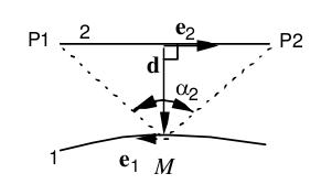
with \(n=\frac{{e}_{2}\wedge d}{d}\), \(d=\parallel d\parallel\), \(\parallel d\parallel =1\)
In the particular case of the infinite right secondary conductor, \({\alpha }_{1}\) and \({\alpha }_{2}\) tend to \(\frac{\pi }{2}\), we then have:
Topological assignment:
◆ TOUT, GROUP_MA
The main conductor relies on all or part of the mesh made up of linear elements in space.
Components:
◆ FX, FY, FZ
In this case where there are several secondary conductors that are infinite and parallel to the main conductor (keywords COUR_PRIN and COUR_SECO in the command DEFI_FONC_ELEC), the components \((\mathit{fx},\mathit{fy},\mathit{fz})\) of the direction of the Laplace force are directly specified, which must be normalized to \(1\) (i.e. \({\mathit{fx}}^{2}+{\mathit{fy}}^{2}+{\mathit{fz}}^{2}\mathrm{=}1\)).
◆ POSITION = 'PARA'/'FINI'/'INFI'
Specify how to define the position of the second driver.
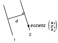
◆ POSITION =' PARA '
For a secondary conductor that is infinite and parallel to the main conductor, there are then two ways to define the secondary conductor.
◆ TRANS =( ux, uy, uz)
(ux, uy, uz) will define the translation leading from the main conductor \(1\) to the secondary conductor \(2\).

◆ DIST = d
  POINT2 = (x2, y2, z2)
The secondary conductor \(2\) is defined by its distance \(d\) from the main conductor \(1\) and a second point (x2, y2, z2).
◆ POSITION =' FINI '
For a secondary conductor that is finite and not parallel to the main conductor.
◆ POINT1 = (x1, y1, z1)
◆ POINT2 = (x2, y2, z2)
Secondary conductor \(2\) is defined by two points (x1, y1, z1) and (x2, y2, z2) corresponding to its ends.
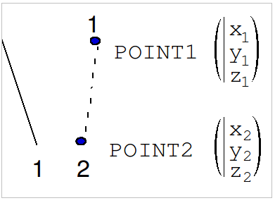
It is best to choose POINT1 and POINT2 such that the current flows from POINT1à POINT2.
◆ POSITION = 'INFI'
For an infinite secondary conductor that is not parallel to the main conductor.
◆ POINT1 = (x1, y1, z1)
◆ POINT2 = (x2, y2, z2)
Secondary conductor \(2\) is defined by two points (x1, y1, z1) and (x2, y2, z2).
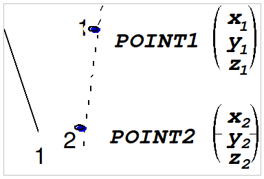
It is best to choose POINT1 and POINT 2 such that the current flows from POINT1 to POINT 2.
7.14. Keyword VECT_ASSE#
VECT_ASSE = fiel_no
The keyword factor VECT_ASSE can be used to apply a second member in the form of a CHAM_NO. This CHAM_NO is passed to these commands via the load name. The chamno movement field is of type cham_no. It may have come from CREA_CHAMP or may have been calculated elsewhere.