3. Definition of the quantities produced#
3.1. Structure element coordinate system#
The figure shows the coordinate system associated with the structural element. Axis \(X\) represents the neutral axis of the structural element. The mechanical characteristics are necessarily given in the main axes of the right section [R3.08.01] of the element: \({Y}_{\mathit{principal}}\) and \({Z}_{\mathit{principal}}\).
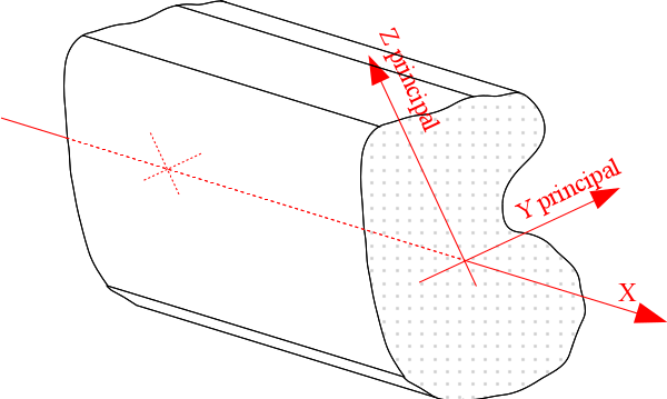
Figure 3.1-a: Structure element coordinate system .
3.2. Markers used for geometric characteristics#
Two reference points are used:
the \(\mathit{OYZ}\) coordinate system for describing the 2D mesh;
the main inertia coordinate system \(\mathrm{Gyz}\). in the right section, whose name corresponds to that used in the description of neutral fiber beam elements \(\mathrm{Gx}\) [U4.42.01].
Note:
The mesh that is at the input of the command is in 2D and must therefore be given in the \(\mathit{oxy}\) axes. Coordinates \(z\) must all be the same. The MACR_CARA_POUTRE command maps the \(x\) and \(Y\) axes to, \(y\) and \(Z\).
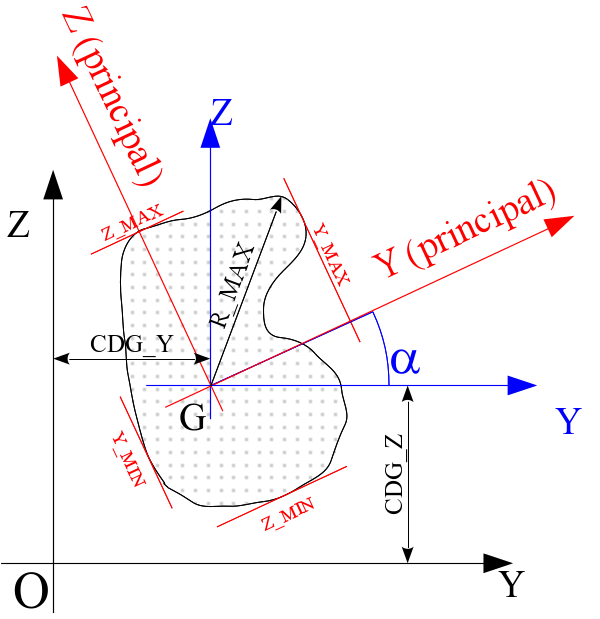
Figure 3.2-a: Definition of geometric quantities relating to a section of a beam.
3.3. Sizes available in the produced table#
3.3.1. Geometric characteristics#
These characteristics are given in the table for the entire mesh and for each group in the lgm list (which can correspond to a half or a quarter of the section if the keywords SYME_Y or SYME_Z are present).
3.3.1.1. Characteristics of the mesh read#
area: A_M
center of gravity position: CDG_Y_M, CDG_Z_M
moments and product of inertia of air, at the center of gravity \(G\) in the \(\mathit{GYZ}\) coordinate system:
IY_G_M IZ_G_M IYZ_G_M
3.3.1.2. Characteristics of the beam section#
area: A
center of gravity position: CDG_Y, CDG_Z
moments and product of inertia of air, at the center of gravity \(G\) in the \(\mathit{GYZ}\) coordinate system:
IY_GIZ_G IYZ_G
main moments of inertia of air in frame \(\mathrm{Gyz}\), usable for calculating the flexural stiffness of the beam: IY and IZ
angle of transition from coordinate system \(\mathit{GYZ}\) to the main inertia coordinate system \(\mathrm{Gyz}\): ALPHA
characteristic distances, in relation to the center of gravity \(G\) of the section for maximum stress calculations: Y_ MAX, Y_ MIN, Z_ MAX, Z_ MIN and R_ MAX.
RY and RZ: maximum of Y_ MIN and Y_ MAX and of Z_ MIN and Z_ MAX.
Y_P, Z_P: point for calculating geometric moments of inertia
IY_P, IZ_P, IYZ_P: geometric moments of inertia in the PYZ coordinate system
IY_P, IZ_P: moments of inertia in the coordinate system \(\mathrm{Pyz}\).
IYR2_G, IZR2_G, IYR2, IZR2, IXR2_P, IYR2_P: characteristics useful for the geometric rigidity matrix of the elements POU_D_TG and POU_D_TGM. For more details on the definition of quantities see [R3.08.04]:
\({I}_{\mathrm{yr}}^{2}={\int }_{S}y({y}^{2}+{z}^{2})\mathrm{dS}\) \({I}_{\mathrm{zr}}^{2}={\int }_{S}z({y}^{2}+{z}^{2})\mathrm{dS}\)
3.3.2. « Mechanical » characteristics#
These characteristics are provided in the table for the entire mesh and for each mesh group in the lgm list.
3.3.2.1. Torsion characteristics#
torsional constant: JX
Solving a stationary thermal problem with unknown \(\mathrm{\varphi }\) makes it possible to determine the torsional constant and the shear stresses.
Note:
When the section is made up of thin elements (tubes, reconstituted sections,…) *, it is necessary to have several meshes in this thickness in order to correctly calculate the characteristics related to the twist.
The torsional characteristics are obtained by the resolution \(\mathrm{\Delta }\mathrm{\varphi }\) on the section, so the mesh must be able to solve this equation.
It is necessary to have more than three linear meshes or two meshes squared in the thickness to solve correctly \(\mathrm{\Delta }\mathrm{\varphi }\) **.In case of doubt about the value found, it is possible to obtain an approximate value,* by applying the formula given in [1, p *p. 200, table 3.6.5] . *
torsional radius: RT
The radius of torsion \(\mathrm{Rt}\) may vary along the outer contour; in fact, for any section, the shear due to the twist varies along the edge. We choose to take the value of \(\mathrm{Rt}\) leading to the maximum shears on the outer edge, that is to say the maximum value of \(\mathrm{Rt}\) (in absolute value) on the outer contour. In addition, if the section is honeycombed, we have several « several radii of torsion »: \(\mathrm{Rt}=2\ast A(k)/L(k)\) (where \(A(k)\) represents the area of the cell \(k\) and \(L(k)\) its perimeter).
If we are simply looking for the maximum shear value, we must take the maximum of the \(\mathrm{Rt}\) values obtained on the outer edge and on the cells.
Position of the center of torsion (point \(C\)) in the GYZ coordinate system: PCTY and PCTZ. From this we deduce the eccentricity of the center of torsion (component of \(\mathrm{CG}\) in the main inertia coordinate system Gyz): EY and EZ.
Warpage constant (usable for models POU_D_TG and pou_d_tgm with 7 degrees of freedom): JG.
3.3.2.2. Shear characteristics#
The coefficients \({A}_{y}\) and \({A}_{z}\) are given, in the main inertia coordinate system \(\mathrm{Gyz}\), in the form of the ratio (\(>1\)) of the total area to the area actually sheared.
3.4. Assigning quantities in AFFE_CARA_ELEM#
The characteristics contained in this table and that can be used in AFFE_CARA_ELEM have the same names as the characteristics expected under the CARA keyword of the AFFE_CARA_ELEM command.
The results calculated by MACR_CARA_POUTRE can simply be sent to AFFE_CARA_ELEM via the TABLE_CARA keyword.