2. Presentation of the problem#
2.1. Structure geometry#
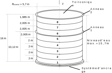
The problem, in the case of a typical tarp, can be represented geometrically as [bib2]:

|
Figure -a: Schematic representation of a real tarpaulin |
The tarpaulin shown is composed of 8 cylindrical shells, each approximately \(2m\) in height, which are welded together to form the cylindrical wall of the tank. The thickness, which is constant per shell, decreases when one goes from a shell to the one that overhangs it. This particular arrangement makes it possible to optimize the thickness of the shells, as a function of the hydrostatic pressure exerted by the fluid contained and which varies linearly with depth.
Given the very low thicknesses of the shells (approximately \(4\) to \(5\mathrm{mm}\)), it is chosen to model the metal walls by thin volume shells (COQUE_3D).
These elements have as geometric support a quadrilateral with 9 nodes.
Some donors do not know how to generate this type of element but offer meshes with more traditional 8-node quadrilaterals. We therefore define the middle nodes in*Code_Aster* with the following command:
MAILLA2 = CREA_MAILLAGE (MAILLAGE = MAILLA01,
MODI_MAILLE =_F (GROUP_MA =” RESERVOIR “,
OPTION =” QUAD8_9 “,
PREF_NOEUD =” NSQ “,
PREF_NUME =1,),);
We then make sure that the normals are oriented correctly:
MAILLA2 = MODI_MAILLAGE (reuse = MAILLA2, MAILLAGE = MAILLA2,
ORIE_NORM_COQUE = _F (GROUP_MA =
(“VIROLE”, “TFC2”),
VECT_NORM = (0., -1.,0. ),
GROUP_NO = “OR”,),
MODELE = MODELE0, INFO = 2,)
We can then define the definitive MODELE model based on solid shells.
The geometric characteristics specific to the structural elements used are defined (COQUE_3D). Shell by shell, we give the thicknesses and the orientation of the marks. It is particularly necessary to be careful to ensure coherence between the axes of the references and the material characteristics when one is in an orthotropic case (case of reinforcement). Likewise, for this reinforcement, the eccentricity can be used to take into account its actual arrangement on the outside of the metal shell (its mean surface cannot therefore be confused with that of the shell supporting it):
CARAELEM = AFFE_CARA_ELEM (MODELE = MODELE,
COQUE = (_F (GROUP_MA = (“SURF0”,),
EPAIS = 7.13E-3,
ANGL_REP = (0., 90.),
A_ CIS = 0.8333,
COEF_RIGI_DRZ = 1.E-05,
EXCENTREMENT = 0. ,
INER_ROTA = “OUI”,
MODI_METRIQUE = “OUI”,),
…
_F (GROUP_MA = (“ANNEAU”,),
EPAIS = 1.E-2,
ANGL_REP = (0., 0.),
A_ CIS = 0.8333,
COEF_RIGI_DRZ = 1.E-05,
EXCENTREMENT = 0. ,
INER_ROTA = “OUI”,
MODI_METRIQUE = “OUI”,),
_F (GROUP_MA = (“TFC2”,),
EPAIS = (1. * 1.72E-3),
ANGL_REP = (0., 90.),
A_ CIS = 0.8333,
EXCENTREMENT = -4.425E-3,
INER_ROTA = “OUI”,
MODI_METRIQUE = “OUI”,),),)
2.2. Materials used#
The sheet metal is made of austenitic stainless steel A240 type 304L and the bolts will be considered to be made of A42 steel.
For A240 steel, various elastoplastic laws with non-linear isotropic work hardening (in the form of traction curves) are proposed. The definition of work hardening based on traction curves, without information on discharge, is well suited to applications where the load is increasing monotonic, which is what we are going to assume in our case (cf. § 3.1):
A5= DEFI_FONCTION (NOM_PARA =” EPSI “,
VALE =( 0.00097, 191820000., 0.00116, 221740000. ,
0.00138, 247020000., 0.00167, 267090000. ,
0.00207, 285920000., 0.0029, 304530000. ,
0.00365, 314300000., 0.00468, 322090000.),
PROL_DROITE =” LINEAIRE “,
PROL_GAUCHE =” LINEAIRE “,);
#
MAA240 = DEFI_MATERIAU (ELAS = _F (E = 1.98E11,
NAKED = 0.3,
RHO = 7900.,),
TRACTION = _F (SIGM = A5,),)
This behavior relationship is of the type “VMIS_ISOT_TRAC” in the nonlinear resolution operator used.
The plastic behavior of grade A42 will not be taken into account at first. In fact, the elastic limit is higher than for 304L and the parts made of this material are more massive, which leads to lower stress levels. The hypothesis of purely elastic isotropic behavior is therefore admissible for the corresponding material, named MAA42.
In the case where we add a carbon fiber fabric reinforcement (TFC), we model it by an orthotropic elastic material (the plasticity threshold is never reached for our loads):
MATFC = DEFI_MATERIAU (ELAS_ORTH = _F (E_L = 1.E10,
E_T = 1.E12,
G_LT = 3.E9,
NU_LT = 0.3,
RHO = 2500.,),)