4. Validating the visualization of internal variables#
4.1. Principle#
We will check the correct printing of the internal variables by their name produced by the print command IMPR_RESU.
IMPR_RESU (FORMAT =” MED “, RESU =_F (RESULTAT = RESU, IMPR_NOM_VARI =” OUI”,),)
The feature is activated by default (keyword IMPR_NOM_VARI =” OUI “by default). In this case, file MED contains a field VARI_ELGA_NOMME which is the image of field VARI_ELGA but with explicit component names.
This feature allows you to associate an internal variable name of the standard code_aster type (NOM_CMP =”V1”, “V2”, “V3”, etc.) with an explicit internal variable name (NOM_VARI).
Correspondence is automatic. At the beginning of the non-linear command (STAT_NON_LINE or DYNA_NON_LINE), we have the list of internal variables and their names.
Verification procedure: in the Paravis module, you must check the correspondence between the components of VARI_ELGA (V1, V2, V3) and the components of VARI_ELGA_NOMME (corresponding).
4.2. Validation procedure — Mono-behavior case#
A single behavior is considered over the entire mesh.
1/ Import the test case given in the following paragraphs.
2/ To retrieve the result file, we define the unit 80 as the result and the name of the file in .rmed format as the output.
3/ In the ParaVis module, after loading the defined result file, apply a ELGA field To Surface filter.
The visualization is then done by selecting the field, the component and the moment.
4/ Then check:
the name of the components of type VARI_ELGA_NOMME given in the table,
the correspondence between VARI_ELGA and VARI_ELGA_NOMME (the two fields must produce the same renderings, according to the correspondence of the components given in the table),
and the proposed rendering in the attached figure.
4.2.1. Test wtnp119b#
Type of test: validation of composite behaviors like THM
Number of internal variables: 3
Component name correspondence:
U2______ VARI_ELGA |
U2______ VARI_ELGA_NOMME |
V1 |
|
V2 |
|
V3 |
|
Graphic validation: instant=1.0 — Result U2______ VARI_ELGA_NOMME/RHOLIQ — U2______ VARI_ELGA /V

Figure 4.2.1-1: wtnp119b test
4.2.2. HSNV102A Test#
Type of test: validation of metallurgical behaviors with phase names
Number of internal variables: 8
Component name correspondence:
U_______ VARI_ELGA |
U_______ VARI_ELGA_NOMME |
V1 |
|
V2 |
|
V3 |
|
V4 |
|
V5 |
|
V6 |
|
V7 |
|
V8 |
|
Graphic validation: instant=90.0 — Result U_______ VARI_ELGA_NOMME/INDIPLAS — U_______ VARI_ELGA /V8

Figure 4.2.2-1: hsnv102a test
4.2.3. SSNA303a Test#
Type of test: validation of composite behaviors with SIMO_MIEHE
Number of internal variables: 8
Component name correspondence:
UR____VARI_ELGA |
|
V1 |
|
V2 |
|
V3 |
|
V4 |
|
V5 |
|
V6 |
|
V7 |
|
V8 |
|
Graphic validation: INST =1.0 — UR result — UR____VARI_ELGA_NOMME/SM2 — UR____VARI_ELGA /V4

Figure 4.2.3-1: ssna303a test
4.3. Validation procedure — The case of multi-behavior#
Several behaviors are considered throughout the mesh.
The verification procedure is different, because in this case VARI_ELGA cannot provide usable results. Only VARI_ELGA_NOMME makes sense.
The presence of the components is checked:
7 components for VARI_ELGA (from V1 to V7);
8 components for VARI_ELGA_NOMME: EPSPEQ, INDIPLAS, XCINXX,, XCINYY,, XCINZZ, XCINXY, XCINXZ, XCINYZ.
The zzzz400a test case is considered.
To retrieve the result file, we define the unit 80 as the result and the name of the file in .rmed format as the output.
In the ParAvis module, after loading the defined result file, apply a ELGA field To Surface filter.
The visualization is then done by selecting the field, the component and at the moment 5000.
For RESU20__VARI_ELGA_NOMME/EPSEQ, the variable only exists on the left side of the mesh (see figure), the rest is zero.
For RESU20__VARI_ELGA_NOMME/XCINXX, the variable only exists on the right side of the mesh (see figure), the rest is zero.
For RESU20__VARI_ELGA_NOMME/INDIPLAS, the variable is common to both behaviors. We generate the scale over the entire transient (two moments), and the field must be 1 out of TOUT the mesh.
The following views are obtained:

Figure 4.3-1: zzzz400a test, variable EPSEQ

Figure 4.3-2: zzzz400a test, variable XCINXX
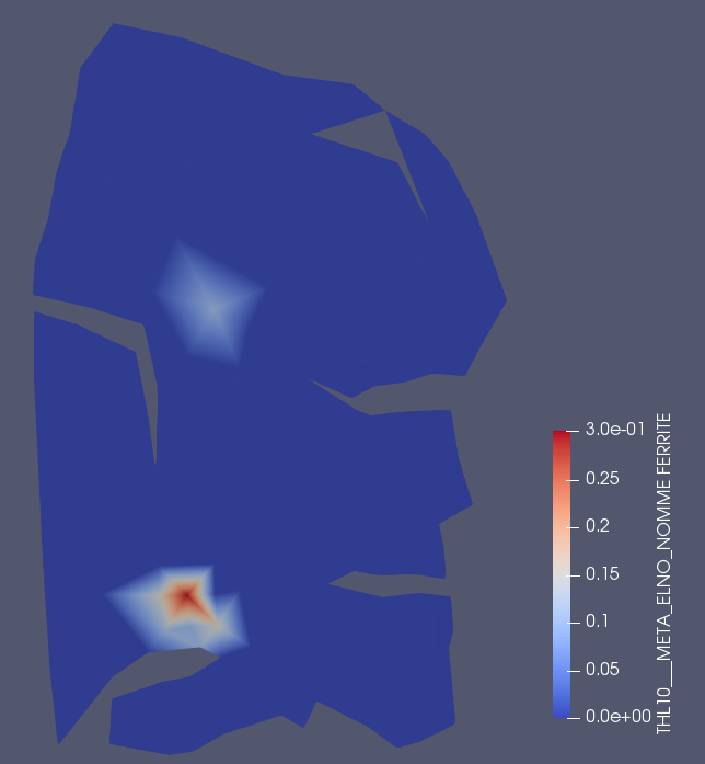
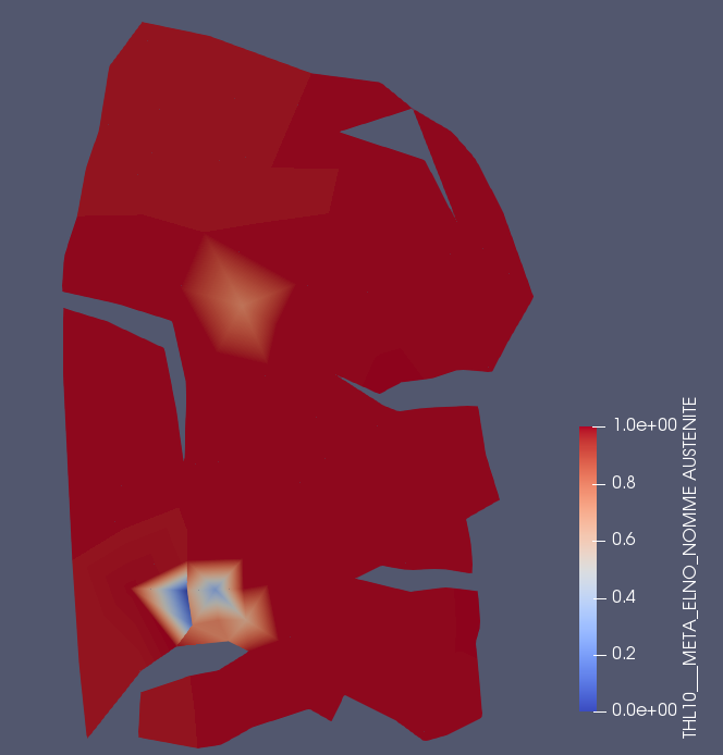
4.4. Validation procedure — Metallurgy case#
Here we validate the printing of field META_ELNO_NOMME in MED format. For this purpose, the ttna200a test is used. It is proposed to check two components named: FERRITE and AUSTENITE. We place ourselves at the last moment (order number 91).
In the command file, add the following print command:
IMPR_RESU (FORMAT =” MED “, RESU =_F (RESULTAT = THL10))
To retrieve the result file, we define the unit 80 as the result and the name of the file in .rmed format as the output.
In the ParaVis module, after loading the result file, apply a ELNO field To Surface filter.
The visualization is then done by selecting:
field THL10___META_ELNO_NOMME for each of the FERRITE and AUSTENITE components.
At the last moment 18.7.
The following views are obtained:
|
|
Figure 4.4-1: ttna200a test, variable FERRITE |
Figure 4.4-2: ttna200a test, variable AUSTENITE |