2. Description of the Bielles-Tirants method#
2.1. Introduction and motivation#
In areas of discontinuity of structural elements, i.e. subject to point loads or possessing abrupt changes in geometry, conventional methods of flexural analysis seem to no longer be sufficient [Thompson, 2002]. These areas are generally reinforced using best practice rules based on experience or empirical guidelines.
The tie rod (BT) method is a rational design procedure for the reinforcement calculation of local regions of reinforced concrete structures (called D zones for discontinuity); the procedure is based on simple mechanical formulations and hypotheses to be easily applied in the design.
In general, the BT method concerns the idealization of areas of discontinuity by means of an internal lattice capable of representing the distribution and the path of forces within the structure. The lattice is composed of:
Connecting rods (compression elements) that model the compression zones of concrete,
Tie rods (elements in tension) that model the traction in the steel frame,
Nodes that represent the areas of interconnection of the elements or the areas anchored in the concrete.
Connecting rods and tie rods are linear elements that carry only axial forces. This truss mechanism should properly balance the loads applied to the system. System failure is therefore dictated by the failure of one or more of its elements or also defined by excessive compression stresses in the connecting rods or in the nodes. Ideally, only the first failure mode should occur.
2.2. Regions of discontinuity#
The basic principles of the theory of curvilinear structures mean that a linear distribution of deformations occurs across the depth of an element, that is, that plane sections remain flat. The element is therefore dominated by flexural behavior, and the design can proceed section by section; this type of element is commonly referred to as regions B. For the design of flexural elements, the compressive stresses are classically assumed on a rectangular stress block, while the tensile stresses are assumed to be taken up by the longitudinal reinforcements.
On the other hand, the D regions (« D » meaning discontinuity) are located near geometric charges or discontinuities. Applied loads, support reactions, and abrupt geometric changes are discontinuities that disturb the distribution of stresses near where they act. Thick beams, openings, and corbels are examples of the geometric discontinuities that correspond to the existence of D regions.
A characteristic of the D regions is that the forces through the limb depth have a non-linear profile, so the assumptions underlying flexural design methods are not validated. According to the Saint-Venant principle, an analysis of elastic stresses indicates that the stresses due to axial forces and to bending, approximate a linear distribution at a distance approximately equal to the depth of the limb, \(h\), away from the discontinuity. In other words, a non-linear distribution of stresses exists according to the depth of a member from the point where the discontinuity is introduced [Schlaich et al., 1987].
2.3. Fundamental principles#
A BT model design adheres to two principles:
the resulting lattice model must be in balance with the system of external forces
the concrete element must have sufficient deformation capacity to guarantee the assumed distribution of forces [Schlaich et al., 1987]; the correct anchor length of the reinforcement is an implicit requirement in order to guarantee the necessary ductility.
In addition, the compressive stresses developed in the concrete must not exceed the strength of the concrete, and the traction developed at the reinforcements must be less than the resistant force of the steel section. If all of the requirements mentioned are met, the application of the BT method should result in a conservative design [Williams et al., 2012].
2.4. Application#
The following paragraphs describe the manual application of the BT method.
2.4.1. Zoning#
The first step is to define whether the BT method is a good alternative to solve the problem. Based on the Saint-Venant principle, the structure can be divided into B and D regions. The MBT design process should be used to design the sections that qualify as D regions.
2.4.2. Definition of boundary conditions#
The second step is to determine the load cases that the structure should support. If the structure is composed of both B regions and D regions, only D regions will be designed using the BT method. In this way, each region D should be treated as an isolated element whose nodal boundary conditions come from their interaction with adjacent elements and from the overall reaction of the supports of the structure for the load cases under consideration (Figure 2.4.2-a): the forces acting at the boundaries of region D concrete the boundary conditions for the design of the BT model.
The internal forces and moments at the interfaces between regions B and D can be assumed to be punctually concentrated and should be applied at the limit of region D (Figure 2.4.2-a). An overall elastic analysis of the structure should be performed in order to determine the support reactions and interface loads for the various D regions.
Considering that the elements of the BT model cannot withstand certain types of loads (for example, moments and distributed loads), some modifications may be required to produce an equivalent loading system.
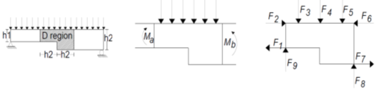
Figure 2.4.2-a: Local area of a beam with variable thickness. Global element (left), Boundaries of region D (center), and isolated model (right).
2.4.3. Model definition#
Based on the system of equivalent point loads derived from the previous step, the engineer projects the connecting rods and tie rods as straight elements from one node to another in order to develop a stable structure. This process may eventually include the interaction of all initial nodes and may also include secondary nodes based on designer criteria. For this step, a continuous finite element model, solved in linear elasticity, is commonly used in order to visualize the direction of the main stresses in the structure and align the elements of the BT model according to the stress trajectories [Schlaich et al., 1987].
2.4.4. BT model analysis and element section#
The cross section of each element of the BT model must be sufficient to safely withstand the force that passes through it, without exceeding the elastic limit of steel (for tie rods) or the limit strength in concrete (for connecting rods). As for a conventionally reinforced structure, the minimum cross section, \({A}_{\mathit{st}}\), of an element subjected to axial force can be determined using the following equation:
In this expression:
\({F}_{u}\) corresponds to the greatest force applied in the element
\(R\) is the strength of the material in question (\({\mathrm{\sigma }}_{y}\) for steel and \({\mathrm{\sigma }}_{c}\) for concrete)
\(\mathrm{\varphi }\) a safety factor specified in the appropriate regulations
2.4.5. Node check#
Because of the level of stress that must be balanced in a small volume of concrete, the nodes of the truss structure are the most heavily stressed regions in a BT model. In particular, nodes are just a simplified idealization of a more complex reality and the definition of their geometry is also based on the designer’s criteria. Ideally, the nodes can be designed so that the stress on all faces is the same. If the stress is the same, the ratio of the lateral surface area is proportional to the force applied. In this case, the node is called a hydrostatic node: the main stresses are equal on all sides and the shear stresses disappear.
Commonly, a classification of the type of nodes is made according to the nature of the elements that converge on a connection zone. Depending on the sign of the converging forces, the node may be called CCC, CCT,, CTT, or TTT (C for compression forces and T for tension forces). If more than three elements converge in a node, it is recommended to merge force groups in order to reduce their number. However, this is not always possible and other possible types of nodal combinations are also accepted (e.g. CCTT, CCCC).