3. Benchmarks and notations#
By default, the local coordinate system for beams in Code_Aster is the \(X\) axis. We keep this convention.
The cracked rotor element is characterized by:
its \(\mathrm{2L}\) length;
its \(R\) radius;
the position of the cracked section (in the middle of the rotor)
The following mechanical characteristics are considered:
Young’s modulus: \(E\)
Inertia of the non-cracked beam: \(I\)
The classical description of the kinematics of beams is followed. The perpendicular sections of the beam remain straight and their rotation is described by:
\(\theta =\left(\begin{array}{c}{\theta }_{y}(x)\\ {\theta }_{z}(x)\end{array}\right)\)
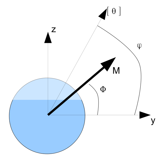
The beam is subjected to a bending moment:
\(M\mathrm{=}(\begin{array}{c}{M}_{y}\\ {M}_{z}\end{array})\), which can open or close the crack.
The deformation energy of the cracked rotor part under the imposed flexural load is noted \({W}^{f}(M)\).
The deformation energy provided by the discrete element modeling the crack for a rotational discontinuity \([\theta ]\) is noted \({W}^{d}([\theta ])\).
The description of the cracked section, although averaged in the beam modeling, requires some attention, however, because the orientation of the response at the crack level is not always the same as that of the force. It depends on the shape of the crack.
Two angles are therefore defined in the coordinate system of the cracked section:
\(\Phi\), the orientation of the effort imposed in the rotating frame of reference;
\(\varphi\), the orientation of the response in the rotating coordinate system.
Finally, we note \(s(M)\) the local flexibility of the equivalent 1D element representing the crack and \(k(\mathrm{[}\theta \mathrm{]})\) its local stiffness.