1. Presentation of the mechanisms involved#
1.1. Global frame of reference and mechanism#
The following shows the local coordinate system with the local axes of the discrete element as well as the force (forces and moments) and displacement (translation and rotation) notations. The arrows always indicate positive values here.
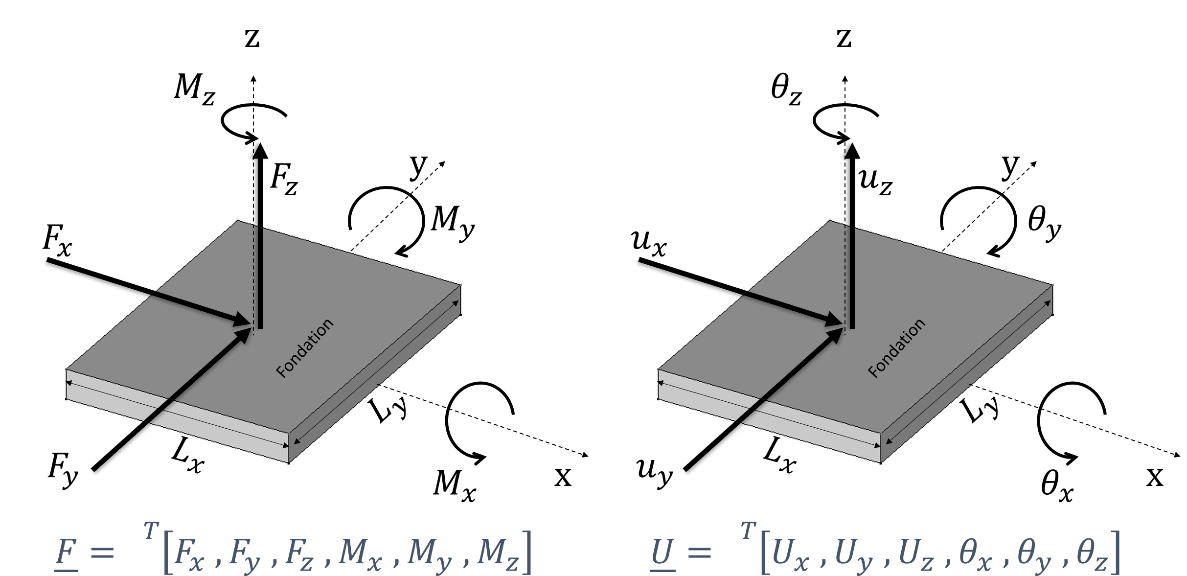
Figure 1.1-1: Foundation’s local benchmark and global effort/displacement scoring
For its part, the following presents the 3 mechanisms involved, the formulation of which is given in the following 3 paragraphs.
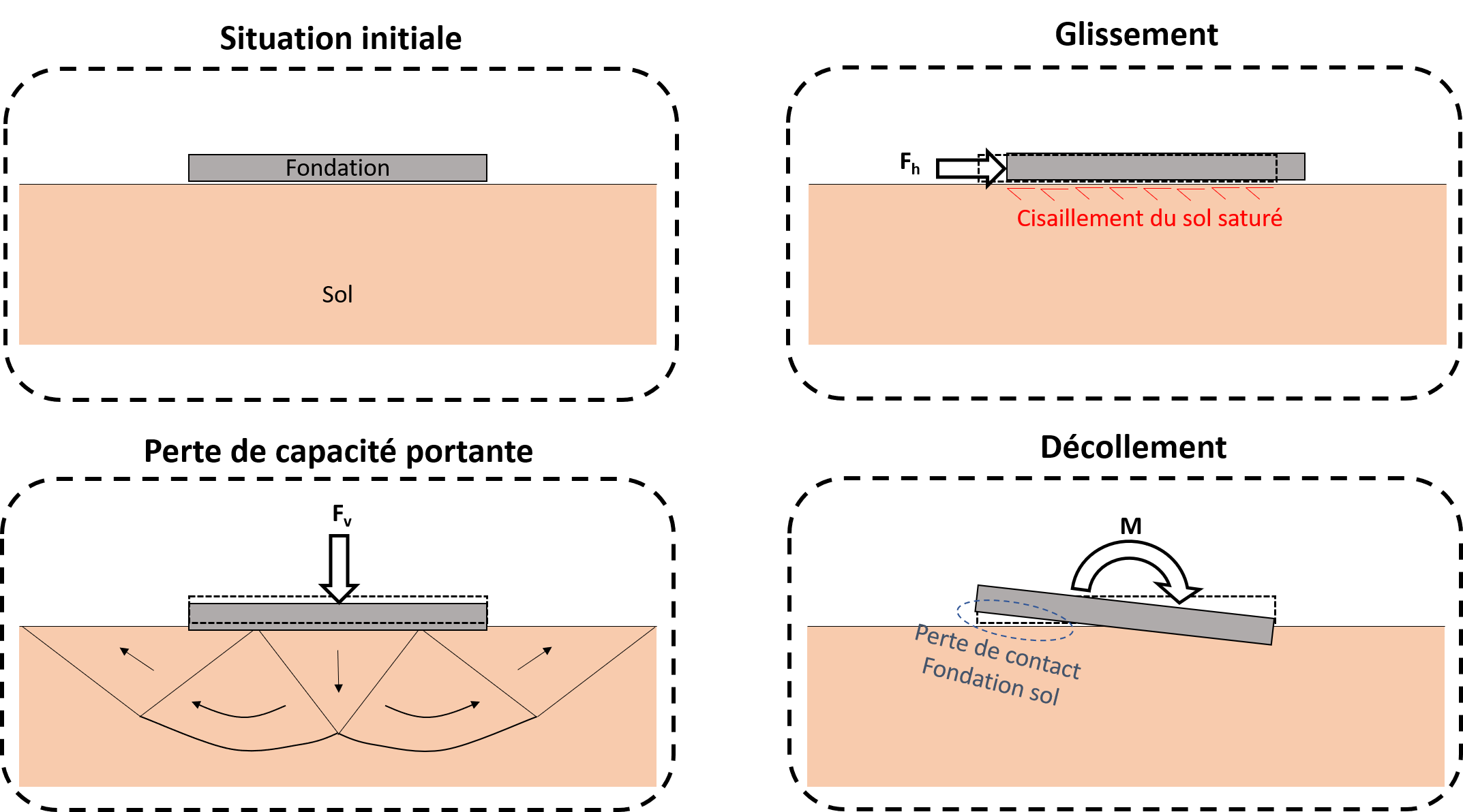
Figure 1.1-2: Schematic diagram of the 3 mechanisms
1.2. Sliding mechanism#
The expression of the plasticity surface of this mechanism is based on the Coulomb friction model. The friction resistance is the sum of a friction term, a function of the vertical force and of a cohesion term calculated on a reduced surface:
\({f}_{s}=\sqrt{{({F}_{x}-{q}_{{h}_{x}})}^{2}+{({F}_{y}-{q}_{{h}_{y}})}^{2}}+{F}_{z}\mathrm{tan}({\varphi }_{inter})-{c}_{inter}{A}^{\text{'}}\)
Where the reduced area is written in the following way taking into account the division by 0:
- math:
{A} ^ {text {“}} = {L}} = {L} _ {x} {L} _ {y}times{begin {array} {cc}hfillleft (1+frac {2| {2| {M} {2| {M} _ {x}} |} {M} _ {x} |} |} {{L} _ {z}}}right)left (1+frac {2| {M} _ {y} |} {{L} _ {x} _ {x} {F} {F} _ {z}}right) & iftext {} {f} _ {z <0hfill\hfill 1& sitext {}left ({F} _ {z} =0right) ettext {} ({M} _ {x} =0) et ({M} _ {y} =0)hfill\hfill 0& sitext {}left ({F} _ {z} >right) ortext {}left (({F} _ {z} =0) and ({M} _ {z} =0) and ({M} _ {x})right)right)hfillend {array}
In the \((-{F}_{z},{F}_{x})\) effort plan, this area is given in the figure below:
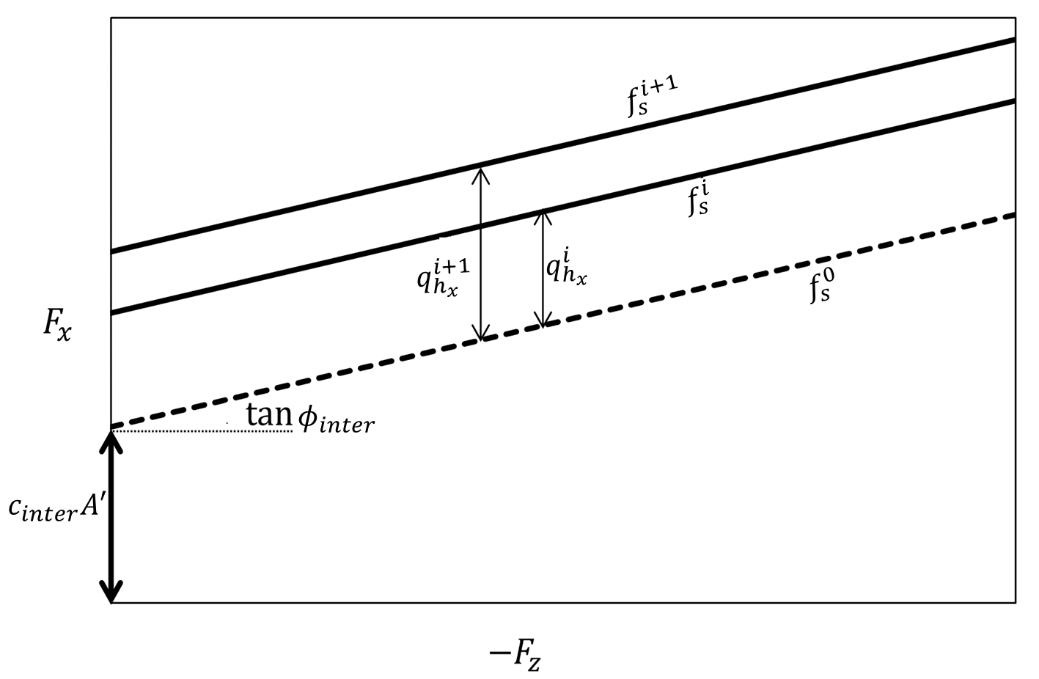
Figure 1.2-1: Evolution of the surface of the sliding mechanism
This failure criterion is associated with a specific plastic displacement noted \(\underline{{U}_{p}^{sl}}\) with the following coordinates:
\(\underline{{U}_{sl}^{pl}}={}^{T}({U}_{x,s}^{pl},{U}_{y,s}^{pl},{U}_{z,s}^{pl},{\theta }_{x,s}^{pl},{\theta }_{y,s}^{pl},{\theta }_{z,s}^{pl}=0)\)
The sliding work hardening variable \({Q}_{\mathit{sl}}={}^{T}({q}_{{h}_{x}},{q}_{{h}_{y}})\) are added to take account of cyclical effects. These variables change when the point representing the torsor of forces at the foundation exceeds surface \(>\). Their evolution is described by the following law of work hardening:
- math:
begin {array} {cc} {mathrm {d} q}} _ {{h} _ {x}} = {H} _ {h}cdot {dU} _ {x, s} _ {x, s} ^ {pl} ^ {pl} ^ {pl}^ {pl}^ {pl}){pl}^ {pl}) {pl} ^ {pl})mathrm {pl}phantom {0} {U} _ {x, s} ^ {pl} =sum {dU} _ {x, s} ^ {pl}text {}mathrm {and}text {v} _ {v} _ {x, s} _ {x, s} _ {pl} _ {pl} =sum | {dU} _ {pl} |\ {mathrm {d}}} _ {h} _ {y}} = {H} _ {h}cdot {dU}cdot {dU} _ {y, s} ^ {pl}text {}mathrm {exp} (-gamma {v} _ {y, s}}} ^ {s}} _ {pl} ={y, s} _ {pl} ={y, s} _ {pl} ={y, s} _ {pl} ={y, s} ^ {pl}} ={y, s}} ^ {pl} ={y, s} ^ {pl}} ={y, s} ^ {pl}} ={y, s} ^ {pl}} ={y, s}} ^ {pl} ={y, s} ^ {pl}}, s} ^ {pl}text {}mathrm {and}text {} {v} _ {y, s} ^ {pl} =sum | {dU} _ {y, s} _ {y, s}} ^ {pl} |end {array}
Which can be noted with the following matrix relationship:
\({\mathrm{d}Q}_{sl}={}^{T}({\mathrm{d}q}_{{h}_{x}},{\mathrm{d}q}_{{h}_{y}}),\text{ }\text{ }\mathrm{d}{U}_{sl}^{pl}=\text{ }{}^{T}\left(\mathrm{d}{U}_{x,s}^{pl},\mathrm{d}{U}_{y,s}^{pl},\mathrm{d}{U}_{z,s}^{pl},\mathrm{d}{\theta }_{x,s}^{pl},\mathrm{d}{\theta }_{y,s}^{pl},\mathrm{d}{\theta }_{z,s}^{pl}=0\right)\)
\({\mathrm{d}Q}_{sl}={H}_{sl}\cdot \mathrm{d}{U}_{sl}^{pl}\text{}\mathrm{avec}\text{ }{H}_{sl}=\left(\begin{array}{cccccc}{H}_{h}\mathrm{exp}(-\gamma {v}_{x,s}^{pl})& 0& 0& 0& 0& 0\\ 0& {H}_{h}\mathrm{exp}(-\gamma {v}_{y,s}^{pl})& 0& 0& 0& 0\end{array}\right)\text{ }\)
\(>\) and \(>\) are two characteristic parameters of this law, defined as follows:
\(>\) is the work hardening module when the mechanism is activated for the first time \(>\). To ensure continuity with elastic behavior, it is recommended to choose \({H}_{h}\) of the same order of magnitude as the stiffness in horizontal translation.
the coefficient \(>\), homogeneous in contrast to a displacement, is calculated so as to have \({\mathrm{d}Q}_{sl}\approx 0\) when \(>\) or \(>\) approaches a limit value \(>\) defined beforehand. Based on the properties of the exponential function, we can estimate that \(\gamma =\frac{5}{{U}_{max,s}^{pl}}\).
1.3. Load-bearing capacity loss mechanism#
The expression of the plasticity surface of this mechanism (abbreviated « CP ») is inspired by the usual criteria. It is based on the justification of the vertical force in relation to a given elastic limit \({V}_{lim}\). This elastic limit is reduced as a function of the inclination and the eccentricity of the load, which are respective functions of the horizontal force and of the moment:
- math:
{f} _ {mathit {CP}} =- {F}}} =- {F} _ {z} - {V} _ {lim} {left (1+frac {sqrt {{F} _ {F} _ {F} {F} {F} {F} {F} {F} {F} {F} {F} {F} {F} {F} {F} {F} {F}} {F} {F} {F} {F} {F}} {F} {F} {F} {F} {F}} {F} {F} {F} {F}} {F} {F} {F} {F}} {F} {F} {F}} {F} {F} {F}} {F} {F frac {2left| {M} _ {x}right|} {{x}right|} {{L} _ {y} {F}}right)left (1+frac {2left| {M} | {M} _ {y}right|} {{y}right|}} {{L} _ {z}}right)
This failure criterion is associated with a specific plastic displacement noted \({U}_{\mathit{CP}}^{pl}\) with the following coordinates:
\({U}_{CP}^{pl}={}^{T}({U}_{x,CP}^{pl},{U}_{y,CP}^{pl},{U}_{z,CP}^{pl},{\theta }_{x,CP}^{pl},{\theta }_{y,CP}^{pl},{\theta }_{z,CP}^{pl}=0)\)
When the point representing the torsor forces of the foundation exceeds the load surface, the surface evolves according to the irreversible vertical compaction using 4 kinematic work hardening variables \({R}_{h,x},\text{}{R}_{h,y},\text{}{R}_{m,x},\text{}{R}_{m,y}\) respectively for the translation along x, the translation according to y, the translation according to y, the rotation according to y, the rotation according to x and the rotation according to x and the rotation according to y, and an isotropic work hardening variable \(R\) with the following vector notation \({Q}_{\mathit{CP}}={}^{T}({R}_{h,x},{R}_{h,y},R,{R}_{m,x},{R}_{m,y})\). The expression for this area becomes:
- math:
`{f} _ {mathit {CP}} =- {F}}} =- {F} _ {z} - ({V} _ {lim} +R)left{begin {array} {c} {left (1+frac {left (1+frac {sqrt {sqrt {sqrt {{left) {sqrt {{left ({F} _ {x}} - {R} _ {h, x}right)} ^ {2} + {left (1+frac {sqrt {sqrt {sqrt {{left ({F}left ({F} _ {x}} - {R} _ {array} {c} {c}} {c} {c}} {left ({F} _ {y} - {R} _ {h, y}right)} ^ {2}}} {{F} _ {z}}right)} ^ {3}left (1+frac {2frac {2left| {2left| {h, y}left| {M, y} {2}}right)} ^ {3}left (1+frac {2left| {2left| {M} | y} {2left| {M} _ {F} _ {z}}right)} ^ {3}left (1+frac {2left| 2left| {M} _ {F} _ {z} _ {z} _ {f} _ {z}}}right)left (1+frac {2left| {M} _ {y} - {R} _ {m, y}right|} {{L} _ {F} _ {F} _ {z}}right){z}}right)text {}mathrm {}}right)text {}mathrm {{si}text {}left (left ({F} _ {F} _ {x} _ {R} _ {h, x}right),left ({F} _ {y} - {R} _ {h, y}right), {F}}right), {F} _right), {F} _ {h, y}right), {F} _ {h, y}right), {F} _ {h, y}right), {F} _ {h, y}right), {F} _ {h, y}right), {F} _ {h, y}right), {F} _ {h, y}right), {F} _ {h, y}right), {F} _ {h, y}} _ {y} - {R} _ {m, x} {m, x}right)right) =left (0,text {} 0,text {} 0,text {} 0,text {} 0,text {} 0right)hfill\ 0text {}mathrm {otherwise}hfillend {array}right) `
The following figures show the evolution of the surface of the criterion for the isotropic work hardening variable and for the kinematic work hardening variables:
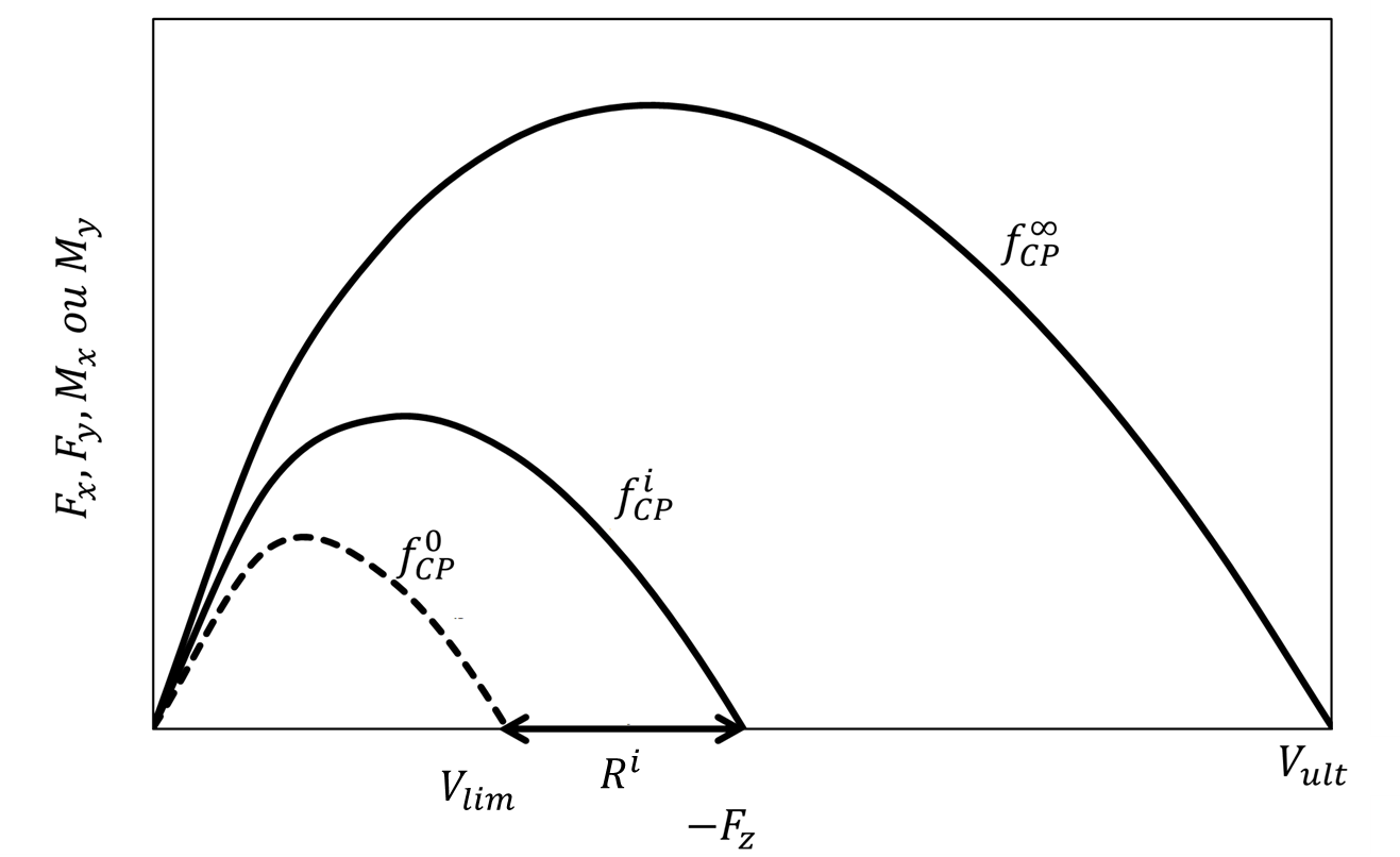
Figure 1.3-1: Evolution of the surface of the CP mechanism with isotropic work hardening
The isotropic work hardening variable is directly deduced from the plastic compaction by the relationship:
- math:
`begin {array} {c} R=left ({V} _ {ult} - {V} _ {lim}right)left (frac {{v} _ {z, CP} ^ {pl}} ^ {pl}}}} {pl}}} R=leftleft ({v}} _ {v}}right)end {array}}right)end {array}}right)end {array}}right)end {array}text {}mathrm {with}text {} {U} _ {z, CP} _ {z, CP} _ {z, CP} ^ {pl}text {}mathrm {and}mathrm {and}text {} {U} _ {z, CP} _ {z, CP} _ {z, CP} {f, CP} {and}mathrm {and}mathrm {and}text {} {U} {U} {U} {and}mathrm {and}text {} {u} {U} {U} {U} {and}text {} {u} {u} {u} {u} {u} {u} {u} {u} {u} {u} {u} {u} {u} {
- math:
{mathrm {D}}} ^ {mathrm {text {“}}}}mathit {where}frac {partial R} {partial {U} _ {z,mathit {CP}}} ^ {CP}}} ^ {CP}} ^ {z}} ^ {mathit {CP}} _ {ult}}left ({V} _ {ult}} - {V} _ {lim}right) {v} _ {r,mathit {CP}}} ^ {pl}} {{left ({v} _ {z,mathit {CP}}} ^ {pl}}} ^ {pl}}} ^ {pl}right)} ^ {2}}text {}mathrm {with}text {with}text {with}text {}{begin {array} {c} {v} _ {z,mathit {CP}}} ^ {pl} =sumleft| {mathrm {d} U} _ {z,mathit {CP}}}}} ^ {CP}}}} ^ {CP}}}} ^ {CP}} _ {z,mathrm {d} U} _ {z,mathit {CP}}}} _ {z,mathit {CP}}}} ^ {CP}}} _ {z,mathit {CP}}}} ^ {CP}}} ^ {CP}}} ^ {CP}}} ^ {CP}}} ^ {CP}}} ^ {CP}}} ^ {CP}}} ^ {CP}}} ^ {CP}}hfill 1&mathrm {si}text {}text {}mathrm {d} {d} {U} _ {z, CP} ^ {pl} >0hfill\hfill -1&mathrm {otherwise}hfillend {array}end {array}
\(>\) and \({v}_{r,\mathit{CP}}^{pl}\) are two characteristic parameters of this work-hardening law, defined as follows:
\(>\) is the load-bearing capacity of the land under the foundation, defined from in situ tests or finite element simulations.
The value of \({v}_{r,\mathit{CP}}^{pl}\) refers to a reference settlement, this value may be of the order of 10% of the small size of the foundation.
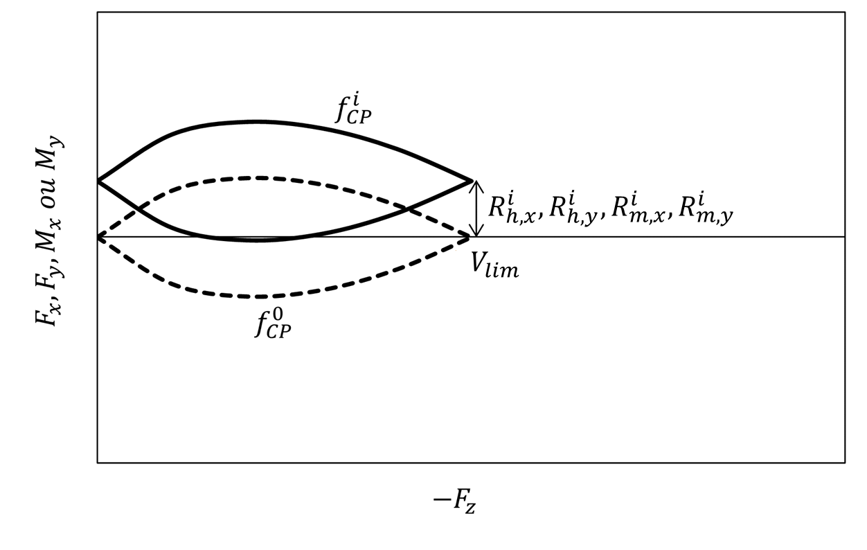
Figure 1.3-2: Evolution of the surface of the CP mechanism with kinematic work hardening only
The evolution of the work-hardening variables is similar to that of sliding (for kinematic work hardening):
\(\left(\begin{array}{c}\mathrm{d}{R}_{h,x}={I}_{h,x}\mathrm{exp}\left(-{\gamma }_{h,x}{v}_{z,\mathit{CP}}^{pl}\right)\mathrm{d}{U}_{x,\mathit{CP}}^{pl}\\ \mathrm{d}{R}_{h,y}={I}_{h,y}\mathrm{exp}\left(-{\gamma }_{h,y}{v}_{z,\mathit{CP}}^{pl}\right)\mathrm{d}{U}_{y,\mathit{CP}}^{pl}\\ \mathrm{d}R=\frac{\partial R}{\partial {U}_{z,\mathit{CP}}^{pl}}\mathrm{d}{U}_{z,CP}^{pl}\text{ }\hfill \\ \mathrm{d}{R}_{m,x}={I}_{m,x}\mathrm{exp}\left(-{\gamma }_{m,x}{v}_{z,\mathit{CP}}^{pl}\right)\mathrm{d}{\theta }_{x,\mathit{CP}}^{pl}\\ \mathrm{d}{R}_{m,y}={I}_{m,y}\mathrm{exp}\left(-{\gamma }_{m,y}{v}_{z,\mathit{CP}}^{pl}\right)\mathrm{d}{\theta }_{y,\mathit{CP}}^{pl}\end{array}\right)\)
Which can be noted with the following matrix relationship:
\(\mathrm{d}{Q}_{\mathit{CP}}={I}_{\mathit{CP}}\cdot \mathrm{d}{U}_{\mathit{CP}}^{pl}\text{}\mathrm{avec}\text{ }\{\begin{array}{c}\mathrm{d}{Q}_{\mathit{CP}}={}^{T}\left(\mathrm{d}{R}_{h,x}\text{ },\text{ }\mathrm{d}{R}_{h,y}\text{ },\text{ }\mathrm{d}R\text{ },\text{ }\mathrm{d}{R}_{m,x}\text{ },\text{ }\mathrm{d}{R}_{m,y}\right)\hfill \\ \mathrm{d}{U}_{\mathit{CP}}^{pl}={}^{T}\left(\mathrm{d}{U}_{x,\mathit{CP}}^{pl}\text{ },\mathrm{d}{U}_{y,\mathit{CP}}^{pl}\text{ },\text{ }\mathrm{d}{U}_{z,\mathit{CP}}^{pl}\text{ },\text{ }\mathrm{d}{\theta }_{x,\mathit{CP}}^{pl}\text{ },\text{ }\mathrm{d}{\theta }_{y,\mathit{CP}}^{pl}\right)\end{array}\mathrm{et}\)
\({I}_{\mathit{CP}}=\left(\begin{array}{ccccc}{I}_{h,x}{e}^{-{\gamma }_{h,x}{v}_{z,\mathit{CP}}^{pl}}& 0& 0& 0& 0\\ 0& {I}_{h,y}{e}^{-{\gamma }_{h,y}{v}_{z,\mathit{CP}}^{pl}}& 0& 0& 0\\ 0& 0& \frac{\partial R}{\partial {U}_{z,\mathit{CP}}^{pl}}& 0& 0\\ 0& 0& 0& {I}_{m,x}{e}^{-{\gamma }_{m,x}{v}_{z,\mathit{CP}}^{pl}}& 0\\ 0& 0& 0& 0& {I}_{m,y}{e}^{-{\gamma }_{m,y}{v}_{z,\mathit{CP}}^{pl}}\end{array}\right)\)
For each kinematic work hardening law, \({I}_{h\text{ }ou\text{ }m,x\text{ }ou\text{ }y}\) and \({\gamma }_{h\text{ }ou\text{ }m,x\text{ }ou\text{ }y}\) are two parameters characteristic of this law, defined as follows:
\(>\) is the work-hardening module when the mechanism is activated for the first time \(\left({U}_{z,\mathit{CP}}^{pl}={v}_{z,\mathit{CP}}^{pl}=0\right)\) To ensure continuity with the elastic behavior, it is recommended to choose \({I}_{\mathit{CP}}\) of the same order of magnitude as the stiffness of the degree of freedom in question.
the coefficient \(>\), homogeneous in contrast to a displacement, is calculated so as to have \({\mathrm{d}Q}_{\mathit{CP}}\approx 0\) when \({v}_{z,\mathit{CP}}^{pl}\) approaches a limit value \({v}_{max,\mathit{CP}}^{pl}\) defined beforehand. Based on the properties of the exponential function, we can estimate that \({\gamma }_{\mathit{CP}}=\frac{5}{{v}_{max,\mathit{CP}}^{pl}}\).
1.4. Peeling mechanism#
The detachment mechanism (only activated if the DETACHMENT parameter is equal to “YES”), considered to be a purely geometric mechanism, is described by a deterioration in the stiffness during rotation. This degradation is supposed to be reversible. Different expressions can be used depending on whether secant stiffness or tangent stiffness is considered. In practice, rotational stiffness: math: {K} _ {mathit {K} _ {K} _ {K} _ {ry} _ {ry} _ {mathit {ry},mathit {ry},mathit {ry}} _,mathit {ry}} _ {ry}} varies according to the eccentrement:math: {e} _ {x, y} =-| {M} _ {ry}},mathit {ry}},mathit {ry}},mathit {ry}}} varies according to the eccentrement:math: {e} _ {x, y} =-| {M} _ {ry}},mathit {ry}},mathit {ry}},mathit {ry}} _ {ry} |/ {F} _ {z}. Below is the value of the secant stiffness in rotation:
- math:
{K} _ {mathit {rx}},mathit {rx}}} ^ {sec} =frac {{M} _ {x}} {{theta} _ {x}} = {K}} = {K}}} = {K}} _ {K} _ {r} _ {x}}} = {K} _ {x}}} = {K} _ {x}} = {K} _ {x}} = {K} _ {x}} = {K} _ {x}} = {K} _ {x}} = {K} _ {x}} = {K} _ {x}} = {K} _ {x}} = {K} _ {x}} = {K} _ {x}}} = {K} _ {| {M} _ {x} |le -frac {{F} _ {F} _ {F} _ {L}} {6}\ hfill -frac {27} {4}cdotfrac {2frac {2left| {2left| {M} _ {F}right|}} {{F}} _ {y}}cdot {left}}cdot {left (1+frac {2left| {M} _ {x}right|} {{F} _ {z} {L} _ {y}}right)} ^ {2}text {}text {}text {} &mathrm {} &mathrm {}mathrm {otherwise}hfillend {array}
- math:
{K} _ {mathit {ry},mathit {ry}},mathit {ry}}} ^ {sec} =frac {{M} _ {y}}} {theta} _ {y}} = {K}}} = {K} _ {mathit {ry}}} = {K} _ {y}}} = {K}}} = {K} _ {y}}} = {K} _ {y}} = {K} _ {y}} = {K} _ {y}} = {K} _ {y}} = {K} _ {y}} = {K} _ {y}} = {K} _ {y}} = {K} _ {y}} = {K} _ {y}} = {K} | {M} _ {y} |le -frac {{F} _ {f} _ {z} {L}} {6}\ -frac {27} {4}cdotfrac {2left {2left ({M} _ {F} _ {y}right)} {{F} _ {z}} {L} _ {x}}cdot {left (1+frac {left (1+frac)} ac {2left ({M} _ {y}right)} {{F}right)} {{F} _ {f} _ {x}}right)} ^ {2}text {} &mathrm {} &mathrm {otherwise}mathrm {otherwise}hfillend {array}
Where \({K}_{\mathit{rx},\mathit{rx}}^{0}\) and \({K}_{\mathit{ry},\mathit{ry}}^{0}\) are the stiffness in rotations without detachment.
This detachment is only implemented under aster code in the form of tangent stiffness:
- math:
{K} _ {mathit {rx}},mathit {rx}}} ^ {tan} =frac {partial {M} _ {x}} {partial {theta} _ {x}} = {x}} = {K}}} = {K}} _ {mathit {rx}}} ^ {0}{begin {array} {cc}}} = {K}}} = {K}} _ {x}} = {K} _ {x}} = {K} _ {x}} = {K} _ {x}} = {K} _ {x}} = {K} _ {x}} = {K} _ {x}} = {K} _ {x}} = {K} _ {x}} = {K} {si} | {M} _ {x} |le -frac {{F} _ {z} {L}} {y}} {6}\ frac {27} {8} {left (1+frac {2left| 1+frac {2left| {M} _ {2left| {M} _ {2left| {M} _ {x}right|} {{F}}} {z} {z} {L} {8}} {8} {left (1+frac {2left| 1+frac {2left| {M} _ {2left| {M} _ {x}right|} {{F} _ {z} {L} {L} {8} {{3} &mathrm {otherwise}hfillend {array}
- math:
{K} _ {mathit {ry},mathit {ry}},mathit {ry}}} ^ {tan} =frac {{M} _ {y}} {theta} _ {y}} = {K}}} = {K} _ {mathit {ry}},mathit {ry}}},mathit {ry}}} ^ {tan} =frac {{M} _ {y}}} {{theta} _ {y}}} = {K}}} = {K}}} = {K} _ {y}}} = {K}}} = {K} _ {y}}} = {K} _ {y}} = {K} _ {y}} = {K} _ {y}} {M} _ {y} |le -frac {{F} _ {f} _ {f} _ {x}} {6}\ frac {27} {8} {left (1+frac {2left| {2left| {M} | left| {M} _ {y}right|}} {M} _ {x}}right)} ^ {3}right)} ^ {3}right)} ^ {3}right)} ^ {3}right)} ^ {3}right text {} &mathrm {otherwise}hfillend {array}
So the moment cannot go beyond the final moment:
- math:
{M} _ {x} ^ {ult} =left|frac {{F} _ {z} _ {y}} {2}right|text {} andtext {} {M}} _ {M} _ {M} _ {M} _ {M} _ {M} _ {M} _ {M} _ {M} _ {M} _ {M} _ {M} _ {M} _ {M} _ {M} _ {M} _ {M} _ {M} _ {M} _ {M} _ {M} _ {M} _ {M} _ {M} _ {M} _ {M} _ {M} _ {M} _ {M} _ {M} _ {M} _ {M} _ {M} _ {M} _ {M}
The variation of the secant and tangent stiffness as a function of the moment are given in the figure below.
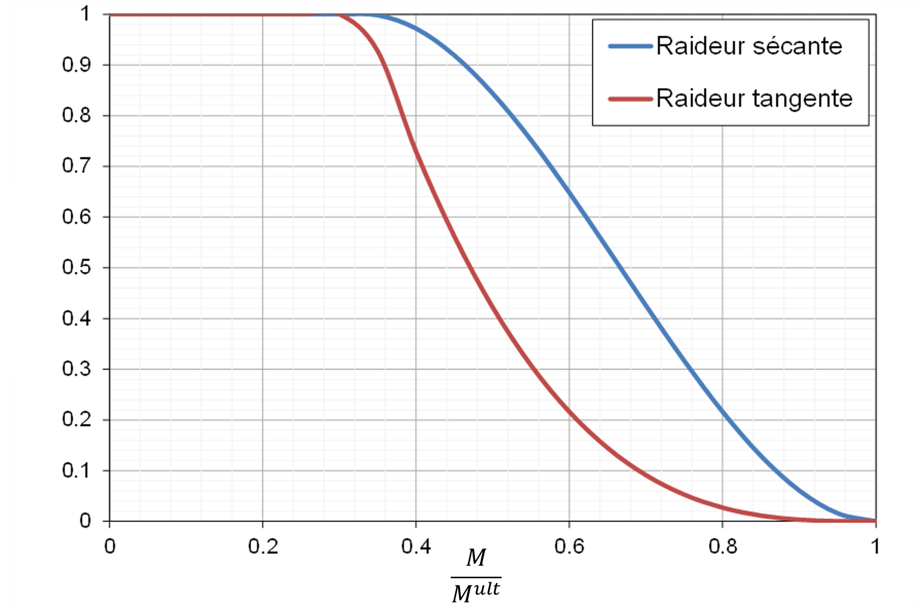
Figure 1.4-1: Rotational stiffness as a function of moment