3. Kinematics specific to twisting with warping#
The kinematics used to represent the displacement of beam sections is identical to that of straight Timoshenko [R3.08.01] beams with respect to tensile - compression, and flexion-shear. We only detail here the twist.
Two possibilities are to be considered for modeling the torsional behavior of non-circular sections [bib], which always produces warping of the right section.
The torsion is free (Saint-Venant twist): the warping of the straight sections is non-zero (it can even be significant for an open thin section), but it is independent of the position on the \(x\) axis of the beam, (constant as a function of \(x\)), and there is no axial stress due to the twist.
Torsion is hampered (Vlassov): the warping is non-zero, and in addition non-uniform axial stresses (whose resulting force is called bi-moment) exist in the beam.
Element POU_D_TG makes it possible to treat these two configurations: the twisting can be free or hindered. The user will have access to warping in both cases, on the other hand, bi-moment will not be zero except in the case of awkward twisting. Note that at the point where the beams are connected, the transmission of warpage depends on the type of connection. In general, twisting in a beam assembly is hampered. Warping can then be blocked at the connection points.
Note:
With elements without warpage modeling (POU_D_T, * POU_D_E), we can treat the case of free twisting (displacements other than warping will be correct), but not the case of hampered twisting.
It is possible to decouple the effects of torsional and flexure in a local coordinate system (translated from the main inertia coordinate system) originating from the center of torsion. The center of torsion is the point that remains fixed when the section is subjected to the torsional moment alone. It is also called the shear center because a force applied at this point does not produce a rotation around \(x\).
The movements in the plane of the section will therefore be expressed in this coordinate system. The axial displacements remain expressed in the main inertia reference frame linked to the center of gravity \(G\), to maintain a decoupling of the flexural and tension-compression movements.
The displacement of any point in the straight section is then written in general form (free or hampered twisting):
\(\begin{array}{}\left\{\begin{array}{c}u(x,y,z)\\ v(x,y,z)\\ w(x,y,z)\end{array}\right\}=\left\{\begin{array}{c}{u}_{G}(x)\\ 0\\ 0\end{array}\right\}+\left\{\begin{array}{c}z{\theta }_{y}(x)\\ 0\\ w(x)\end{array}\right\}+\left\{\begin{array}{c}-y{\theta }_{z}(x)\\ v(x)\\ 0\end{array}\right\}+\left\{\begin{array}{c}\omega (y,z){\theta }_{x,x}(x)\\ -(z-{z}_{c}){\theta }_{x}(x)\\ (y-{y}_{c}){\theta }_{x}(x)\end{array}\right\}\end{array}\)
Displacement = membrane + flexion/ \(y\) + flexion/ \(z\) + twisting with warping
The components are expressed in the main inertia coordinate system (centered in \(G\)): \(x\) is directed along the axis of the beam, \(y\) and \(z\) are the two other main inertia axes.
The term \(\omega (y,z){\theta }_{x,x}(x)\) represents axial displacement due to warping of the straight section. \(\omega (y,z)\) is the warping function (expressed in \({m}^{2}\), but which has no obvious physical interpretation).
The deformations at any point in the section are then:
\(\begin{array}{}\left\{\begin{array}{c}{\varepsilon }_{\text{xx}}(x,y,z)\\ 2{\varepsilon }_{\text{xy}}(x,y,z)\\ 2{\varepsilon }_{\text{xz}}(x,y,z)\end{array}\right\}=\left\{\begin{array}{c}{u}_{{G}_{,x}}(x)\\ 0\\ 0\end{array}\right\}+\left\{\begin{array}{c}z{\theta }_{y,x}(x)\\ 0\\ {\gamma }_{\text{xz}}(x)\end{array}\right\}+\left\{\begin{array}{c}-y{\theta }_{z,x}(x)\\ {\gamma }_{\text{xy}}(x)\\ 0\end{array}\right\}+\left\{\begin{array}{c}\omega (y,z){\theta }_{x,\text{xx}}(x)\\ ({\omega }_{,y}-(z-{z}_{c})){\theta }_{x,x}(x)\\ ({\omega }_{,z}+(y-{y}_{c})){\theta }_{x,x}(x)\end{array}\right\}\\ {\gamma }_{\text{xy}}(x)={v}_{,x}-{\theta }_{z}\\ {\gamma }_{\text{xz}}(x)={w}_{,x}+{\theta }_{y}\end{array}\)
\(\text{Déformation}=\text{membrane}+\text{flexion}/y+\text{flexion}/z+\text{torsion avec gauchissement}\)
The term \(\omega (y,z){\theta }_{x,\text{xx}}(x)\) is null in the case of free twisting: we actually have \({\theta }_{x,\text{xx}}(x)=0\), since the warping is independent of \(x\). It is not negligible in the case of awkward twisting.
The law of isotropic elastic behavior can be written (assuming plane stresses in the \(y\) and \(z\) directions):
\(\left\{\begin{array}{c}{\sigma }_{\text{xx}}(x,y,z)\\ {\sigma }_{\text{xy}}(x,y,z)\\ {\sigma }_{\text{xz}}(x,y,z)\end{array}\right\}=\left\{\begin{array}{c}E\text{.}{\varepsilon }_{\text{xx}}(x,y,z)\\ G\text{.}2{\varepsilon }_{\text{xy}}(x,y,z)\\ G\text{.}2{\varepsilon }_{\text{xz}}(x,y,z)\end{array}\right\}\)
The generalized efforts in the section are expressed as a function of the constraints for a homogeneous section by [bib]:
\(N(x)=\underset{S}{\int }{\sigma }_{\text{xx}}(x,y,z)\text{ds}\) |
Normal effort |
\({V}_{y}(x)=\underset{S}{\int }{\sigma }_{\text{xy}}(x,y,z)\text{ds}\) |
Sharp effort next \(y\) |
\({V}_{z}(x)=\underset{S}{\int }{\sigma }_{\text{xz}}(x,y,z)\text{ds}\) |
Sharp effort next \(z\) |
\({M}_{y}(x)=\underset{S}{\int }z\text{.}{\sigma }_{\text{xx}}(x,y,z)\text{ds}\) |
Bending moment around \(y\) |
\({M}_{z}(x)=\underset{S}{\int }-y\text{.}{\sigma }_{\text{xx}}(x,y,z)\text{ds}\) |
Bending moment around \(z\) |
\({M}_{x}(x)=\underset{S}{\int }((y-{y}_{c})\text{.}{\sigma }_{\text{xz}}(x,y,z)-(z-{z}_{c})\text{.}{\sigma }_{\text{xy}}(x,y,z))\text{ds}\) |
Torsional moment |
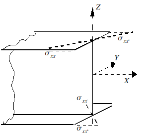
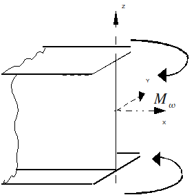
\({M}_{\omega }(x)=\underset{S}{\int }\omega \text{.}{\sigma }_{\text{xx}}(x,y,z)\text{ds}\) |
Bi-moment (associated with warping) |
\({M}_{\omega }(x)\) represents the widespread effort associated with warping. He expresses himself in \({\mathrm{N.m}}^{2}\). We can give an illustration as in [bib] for a beam with a section in \(\text{I}\) (the bi-moment acts here according to \(z\) only):
For isotropic and homogeneous elastic behavior in the section, the generalized forces are therefore expressed directly as a function of the displacements by the following relationships:
\(\begin{array}{}N(x)=E\text{.}S\text{.}{u}_{,x}\\ {V}_{y}(x)={\text{Gk}}_{y}S({v}_{,x}-{\theta }_{z})\\ {V}_{z}(x)={\text{Gk}}_{z}S({w}_{,x}+{\theta }_{y})\\ {M}_{y}(x)=E\text{.}{I}_{y}{\theta }_{\text{y,}x}\\ {M}_{z}(x)=E\text{.}{I}_{z}{\theta }_{z,x}\\ {M}_{x}(x)=G\text{.}J\text{.}{\theta }_{\text{x,x}}\\ {M}_{\omega }(x)=E\text{.}{I}_{\omega }\text{.}{\theta }_{\text{x,xx}}\end{array}\)
where \({k}_{y},{k}_{z}\) are shear coefficients. Warping does not occur in the area of the shear forces, because they are expressed in the coordinate system linked to the shear center. In fact, the warping function \(\omega\) is such that:
\(\begin{array}{}\underset{S}{\int }\omega (y,z)\text{ds}=0\\ \underset{S}{\int }y\text{.}\omega (y,z)\text{ds}=0\\ \underset{S}{\int }z\text{.}\omega (y,z)\text{ds}=0\end{array}\)
And the warping constant is expressed in terms of \(\omega\) by: \(\underset{S}{\int }{\omega }^{2}(y,z)\text{ds}={I}_{\omega }\)