3. Principle of virtual work#
3.1. Deformation work#
The general expression of the 3D deformation work for the plate element offset by the distance \(d\) from the reference plane is equal to:
\({W}_{\text{def}}=\underset{S}{\int }\text{}\underset{d-h/2}{\overset{d+h/2}{\int }}({\mathrm{\epsilon }}_{\text{xx}}{\mathrm{\sigma }}_{\text{xx}}+{\mathrm{\epsilon }}_{\text{yy}}{\mathrm{\sigma }}_{\text{yy}}+{\mathrm{\gamma }}_{\text{xy}}{\mathrm{\sigma }}_{\text{xy}}+{\mathrm{\gamma }}_{x}{\mathrm{\sigma }}_{\text{xz}}+{\mathrm{\gamma }}_{y}{\mathrm{\sigma }}_{\text{yz}})\text{dV}\)
where \(S\) is the mean area, \(\mathit{dV}\mathrm{=}\mathit{dxdydz}\) and where the position in the thickness of the plate varies between \(d‑h\mathrm{/}2\) and \(d+h\mathrm{/}2\).
3.1.1. Expression of the resulting efforts#
By adopting the kinematics of [R3.07.03], we identify the work of inner efforts:
\({W}_{\text{def}}=\underset{S}{\int }({e}_{\text{xx}}{N}_{\text{xx}}+{e}_{\text{yy}}{N}_{\text{yy}}+2{e}_{\text{xy}}{N}_{\text{xy}}+{\kappa }_{\text{xx}}{M}_{\text{xx}}+{\kappa }_{\text{yy}}{M}_{\text{yy}}+2{\kappa }_{\text{xy}}{M}_{\text{xy}}+{\gamma }_{x}{T}_{x}+{\gamma }_{y}{T}_{y})\text{dS}\)
where:
\(N=\left(\begin{array}{c}{N}_{\text{xx}}\\ {N}_{\text{yy}}\\ {N}_{\text{xy}}\end{array}\right)=\underset{d-h/2}{\overset{d+h/2}{\int }}\left(\begin{array}{c}{\sigma }_{\text{xx}}\\ {\sigma }_{\text{yy}}\\ {\sigma }_{\text{xy}}\end{array}\right)\text{dz}\)
\(M=\left(\begin{array}{c}{M}_{\text{xx}}\\ {M}_{\text{yy}}\\ {M}_{\text{xy}}\end{array}\right)=\underset{d-h/2}{\overset{d+h/2}{\int }}\left(\begin{array}{c}{\sigma }_{\text{xx}}\\ {\sigma }_{\text{yy}}\\ {\sigma }_{\text{xy}}\end{array}\right)z\text{dz}\)
\(T=\left(\begin{array}{c}{T}_{x}\\ {T}_{y}\end{array}\right)=\underset{d-h/2}{\overset{d+h/2}{\int }}\left(\begin{array}{c}{\sigma }_{\text{xz}}\\ {\sigma }_{\text{yz}}\end{array}\right)\text{dz}\)
where: |
\({N}_{\mathit{xx}}\), \({N}_{\mathit{yy}}\), \({N}_{\mathit{xy}}\) are the resulting membrane forces (in \(N\mathrm{/}m\)); \({M}_{\mathit{xx}}\), \({M}_{\mathit{yy}}\), \({M}_{\mathit{xy}}\) are the resulting bending forces or moments with respect to the plane of design (in \(N\)); \({T}_{x}\), \({T}_{y}\) are the resulting shear forces or shear forces (in \(N\mathrm{/}m\)). |
3.1.2. Relationship between forces and results: generalized deformations#
The expression deformation work is also written:
\({W}_{\text{def}}=\underset{S}{\int }\underset{d-h/2}{\overset{d+h/2}{\int }}[\text{εC}(\epsilon ,\alpha )\epsilon ]\text{dV}=\underset{S}{\int }\underset{d-h/2}{\overset{d+h/2}{\int }}[\text{eCe}+z\text{eC}\kappa +\text{eC}\gamma +\mathit{z\kappa }\text{Ce}+{z}^{2}\mathit{\kappa C\kappa }+\mathit{z\kappa C\gamma }+\mathit{\gamma C}(e+\mathit{z\kappa }+\gamma )]\text{dSdz}\)
where: \(C(\varepsilon ,\alpha )\) is the local tangent stiffness matrix (symmetric matrix).
This is still written:
\({W}_{\text{def}}=\underset{S}{\int }\underset{-h/2}{\overset{h/2}{\int }}[\text{eCe}+(\zeta +d)\text{eC}\kappa +\text{eC}\gamma +\kappa (\zeta +d)\text{Ce}+(\zeta +d{)}^{2}\mathit{\kappa C\kappa }+\kappa (\zeta +d)\mathit{C\gamma }+\mathit{\gamma C}(e+(\zeta +d)\kappa +\gamma )]\text{dSd}\zeta\)
Using the expression obtained for Wdef in the preceding paragraph, we find the following relationship between the resulting forces and the generalized deformations:
\(\begin{array}{c}N={H}_{m}e+({H}_{\text{mf}}+{\mathit{dH}}_{m})\kappa +{H}_{\mathit{m\gamma }}\gamma \\ M=({H}_{\text{mf}}+{\mathit{dH}}_{m})e+({H}_{f}+2{\mathit{dH}}_{\text{mf}}+{d}^{2}{H}_{m})\kappa +({H}_{\mathit{f\gamma }}+{\mathit{dH}}_{\mathit{m\gamma }})\gamma \\ T={H}_{\mathit{m\gamma }}^{T}e+({H}_{\mathit{f\gamma }}^{T}+{\mathit{dH}}_{\mathit{m\gamma }}^{T})\kappa +{H}_{\text{ct}}\gamma \end{array}\)
with:
\({H}_{m}=\underset{-h/2}{\overset{+h/2}{\int }}\mathit{Hd\zeta }\phantom{\rule{0.5em}{0ex}}\text{}\phantom{\rule{0.5em}{0ex}}{H}_{\text{mf}}=\underset{-h/2}{\overset{+h/2}{\int }}\mathit{H\zeta d\zeta }\text{}\phantom{\rule{0.5em}{0ex}}\text{}{H}_{f}=\underset{-h/2}{\overset{+h/2}{\int }}{\mathit{H\zeta }}^{2}\mathit{d\zeta }\)
\(\phantom{\rule{0.5em}{0ex}}{H}_{\text{ct}}=\underset{-h/2}{\overset{+h/2}{\int }}{H}_{\gamma }\mathit{d\zeta }\phantom{\rule{0.5em}{0ex}}\text{}{H}_{\mathit{m\gamma }}=\underset{-h/2}{\overset{+h/2}{\int }}{H}_{\mathit{c\gamma }}\mathit{d\zeta }\phantom{\rule{0.5em}{0ex}}\text{}{H}_{\mathit{f\gamma }}=\underset{-h/2}{\overset{+h/2}{\int }}{H}_{\mathit{c\gamma }}\mathit{\zeta d\zeta }\phantom{\rule{0.5em}{0ex}}\)
and:
\(e=\left(\begin{array}{c}{e}_{\text{xx}}\\ {e}_{\text{yy}}\\ 2{e}_{\text{xy}}\end{array}\right)\text{,}\kappa =\left(\begin{array}{c}{\kappa }_{\text{xx}}\\ {\kappa }_{\text{yy}}\\ 2{\kappa }_{\text{xy}}\end{array}\right)\text{,}\gamma =\left(\begin{array}{c}{\gamma }_{x}\\ {\gamma }_{y}\end{array}\right)\)
The matrices \({H}_{m}\), \({H}_{f}\), and \({H}_{\mathit{ct}}\) are the membrane stiffness, flexure, and transverse shear matrices, respectively, for the non-eccentric plate element. Matrix \({H}_{\mathit{mf}}\) is a coupling stiffness matrix between the membrane and the flexure for the non-eccentric plate element. It is zero if the plate element is symmetric with respect to its middle sheet. Matrix \({H}_{m}\gamma\) is a matrix of coupling stiffness between the membrane and the transverse distortion. The \({H}_{f}\gamma\) matrix is a coupling stiffness matrix between flexure and transverse distortion. These matrices are zero for zero eccentricity, except in the case of multilayers where they remain non-zero.
For isotropic homogeneous elastic behavior, these matrices have the following expressions:
\({H}_{m}=\frac{\text{Eh}}{1-{v}^{2}}\left(\begin{array}{ccc}1& v& 0\\ v& 1& 0\\ 0& 0& \frac{1-v}{2}\end{array}\right),\text{}{H}_{f}=\frac{{\text{Eh}}^{3}}{\text{12}(1-{v}^{2})}\left(\begin{array}{ccc}1& v& 0\\ v& 1& 0\\ 0& 0& \frac{1-v}{2}\end{array}\right),\text{}{H}_{\text{ct}}=\frac{\text{kEh}}{2(1+v)}\left(\begin{array}{cc}1& 0\\ 0& 1\end{array}\right)\)
and \({H}_{\mathit{mf}}\mathrm{=}{H}_{m}\gamma \mathrm{=}{H}_{f}\gamma \mathrm{=}0\) because there is material symmetry with respect to the \(\zeta \mathrm{=}0\) plane.
For the determination of the shear coefficient \(k\) we refer to [§2.2.3] of [R3.07.03].
The system of relationship between the resulting forces and the generalized deformations can also be written as:
\(\begin{array}{c}N={H}_{m}e+{H}_{\text{mf}}^{\text{'}}\kappa +{H}_{\mathit{m\gamma }}\gamma \\ \begin{array}{c}M={H}_{\text{mf}}^{\text{'}}e+{H}_{f}^{\text{'}}\kappa +{H}_{\mathit{f\gamma }}^{\text{'}}\gamma \\ T\\ T={H}_{\mathit{m\gamma }}^{T}e+{H}_{\mathit{f\gamma }}^{}+{H}_{\text{ct}}\gamma \end{array}\hfill \end{array}\)
with:
\(\begin{array}{c}{H}_{\text{mf}}^{\text{'}}={H}_{\text{mf}}+{\mathit{dH}}_{m}\\ {H}_{f}^{\text{'}}={H}_{f}+2{\mathit{dH}}_{\text{mf}}+{d}^{2}{H}_{m}\end{array}\)
\({H}_{\mathit{fg}}^{\text{'}}={H}_{\mathit{fg}}+{\mathit{dH}}_{\mathit{mg}}\)
Thus, in the case of a plate having material symmetry with respect to plane \(\zeta \mathrm{=}0\), we have \({H}_{\mathit{mf}}\mathrm{=}0\) but \({H}_{\text{mf}}^{\text{'}}={\mathrm{dH}}_{m}\). The eccentricity of the plate leads to a coupling between the terms membrane and flexure.
Notes:
The relationships linking \({H}_{m}\) , \({H}_{f}\) , , \({H}_{\mathit{mf}}\) * ** , * **, * **, , ,, , * , * ** * ** * ** * ** * , to \(H\) and \({H}_{\mathit{ct}}\) to \({H}_{\gamma }\) * are valid regardless of the tangent law of elastic behavior, with anelastic deformations (thermoelasticity, plasticity, … ) .
For a plate made up of \(N\) orthotropic layers in elasticity, the matrices \({H}_{m}\), \({H}_{f}\), \({H}_{\mathit{mf}}\) and \({H}_{\mathit{ct}}\) are written:
\({\mathrm{H}}_{\mathrm{m}}=\sum _{i=1}^{N}{\mathrm{H}}_{\mathrm{mi}},\phantom{\rule{0.5em}{0ex}}\text{}{\mathrm{H}}_{\text{mf}}=\sum _{i=1}^{N}({\mathrm{H}}_{\text{mf}\mathrm{i}}+{\eta }_{i}{\mathrm{H}}_{\mathrm{mi}}),\) \({\mathrm{H}}_{\mathrm{f}}=\sum _{i=1}^{N}({\mathrm{H}}_{\mathrm{fi}}+2{\eta }_{i}{\mathrm{H}}_{\text{mf}\mathrm{i}}+{\eta }_{i}^{2}{\mathrm{H}}_{\mathrm{mi}}),\phantom{\rule{0.5em}{0ex}}{\mathrm{H}}_{\text{ct}}=\sum _{i=1}^{N}{\mathrm{H}}_{\text{ct}\mathrm{i}}\)
where: \({\mathrm{\eta }}_{i}=\frac{1}{2}\left({z}_{i+1}+{z}_{i}\right)\)
\({H}_{\mathit{mi}}\), \({H}_{\mathit{fi}}\), \({H}_{\mathit{mfi}}\), \({H}_{\gamma i}\) represent the membrane, flexure, membrane coupling, and transverse shear matrices for layer \(i\). Note the analogy between these expressions with the form established above:
\(\begin{array}{c}{H}_{\text{mf}}^{\text{'}}={H}_{\text{mf}}+{\mathit{dH}}_{m}\\ {H}_{f}^{\text{'}}={H}_{f}+2{\mathit{dH}}_{\text{mf}}+{d}^{2}{H}_{m}\end{array}\)
It is then deduced that the eccentricity for such a plate is obtained by substituting \({\eta }_{i}+d\) to \({\eta }_{i}\).
3.1.3. Elastic internal energy of plate#
Taking into account the preceding remarks, the elastic internal energy of the plate is more usually expressed for this type of geometry in the following way:
\({\Phi }_{\text{int}}=\frac{1}{2}\underset{S}{\int }[e({H}_{m}e+{H}_{\text{mf}}^{\text{'}}\kappa +{H}_{\mathit{m\gamma }}\gamma )+\kappa ({H}_{\text{mf}}^{\text{'}}e+{H}_{f}^{\text{'}}\kappa +{H}_{\mathit{f\gamma }}^{\text{'}}\gamma )+\gamma ({H}_{\mathit{m\gamma }}^{T}e+{H}_{\mathit{f\gamma }}^{\text{'}T}\kappa +{H}_{\text{ct}}\gamma )]\text{dS}\).
3.1.4. note#
It is possible to choose to express the resulting flexural forces or moments with respect to the mean sheet of the element and no longer with respect to the reference plane. In this case we obtain:
\(N=\left(\begin{array}{c}{N}_{\text{xx}}\\ {N}_{\text{yy}}\\ {N}_{\text{xy}}\end{array}\right)=\underset{d-h/2}{\overset{d+h/2}{\int }}\left(\begin{array}{c}{\sigma }_{\text{xx}}\\ {\sigma }_{\text{yy}}\\ {\sigma }_{\text{xy}}\end{array}\right)\text{dz}\), \({M}^{\text{'}}=\left(\begin{array}{c}{M}_{\text{xx}}^{\text{'}}\\ {M}_{\text{yy}}^{\text{'}}\\ {M}_{\text{xy}}^{\text{'}}\end{array}\right)=\underset{d-h/2}{\overset{d+h/2}{\int }}\left(\begin{array}{c}{\sigma }_{\text{xx}}\\ {\sigma }_{\text{yy}}\\ {\sigma }_{\text{xy}}\end{array}\right)(z-d)\text{dz}\), \(T=\left(\begin{array}{c}{T}_{x}\\ {T}_{y}\end{array}\right)=\underset{d-h/2}{\overset{d+h/2}{\int }}\left(\begin{array}{c}{\sigma }_{\text{xz}}\\ {\sigma }_{\text{yz}}\end{array}\right)\text{dz}\)
and the expression of the work of inner efforts becomes:
\(\begin{array}{c}{W}_{\text{def}}=\underset{S}{\int }\left({e}_{\text{xx}}{N}_{\text{xx}}+{e}_{\text{yy}}{N}_{\text{yy}}+2{e}_{\text{xy}}{N}_{\text{xy}}+{\kappa }_{\text{xx}}({M\text{'}}_{\text{xx}}+{\text{dN}}_{\text{xx}})+{\kappa }_{\text{yy}}({M}_{\text{yy}}^{\text{'}}+{\text{dN}}_{\text{yy}})\right)\mathit{ds}+\\ \underset{S}{\int }\left(2{\kappa }_{\text{xy}}({M}_{\text{xy}}^{\text{'}}+{\text{dN}}_{\text{xy}})+{\gamma }_{x}{T}_{x}+{\gamma }_{y}{T}_{y}\right)\text{dS}\end{array}\)
Using the 3D expression for deformation work, it is then deduced that:
\(\begin{array}{c}N={H}_{m}e+({H}_{\text{mf}}+{\mathit{dH}}_{m})\kappa +{H}_{\mathit{m\gamma }}\gamma \\ {M}^{\text{'}}+\mathit{dN}=({H}_{\text{mf}}+{\mathit{dH}}_{m})e+({H}_{f}+2{\mathit{dH}}_{\text{mf}}+{d}^{2}{H}_{m})\kappa +({H}_{\mathit{f\gamma }}+{\mathit{dH}}_{\mathit{m\gamma }})\gamma \\ T={H}_{\mathit{m\gamma }}^{T}e+({H}_{\mathit{f\gamma }}^{T}+{\mathit{dH}}_{\mathit{m\gamma }}^{T})\kappa +{H}_{\text{ct}}\gamma \end{array}\)
Or again:
\(\begin{array}{c}N={H}_{m}e+({H}_{\text{mf}}+{\mathit{dH}}_{m})\kappa +{H}_{\mathit{m\gamma }}\gamma \\ {M}^{\text{'}}={H}_{\text{mf}}e+({H}_{f}+{\mathit{dH}}_{\text{mf}})\kappa +{H}_{\mathit{f\gamma }}\gamma \\ T={H}_{\mathit{m\gamma }}^{T}e+({H}_{\mathit{f\gamma }}^{T}+{\mathit{dH}}_{\mathit{m\gamma }}^{T})\kappa +{H}_{\text{ct}}\gamma \end{array}\).
The expression of the internal energy of the plate remains of course unchanged. In the case of elasticity, it is always written as:
\({\Phi }_{\text{int}}=\frac{1}{2}\underset{S}{\int }[e({H}_{m}e+{H}_{\text{mf}}^{\text{'}}\kappa +{H}_{\mathit{m\gamma }}\gamma )+\kappa ({H}_{\text{mf}}^{\text{'}}e+{H}_{f}^{\text{'}}\kappa +{H}_{\mathit{f\gamma }}^{\text{'}}\gamma )+\gamma ({H}_{\mathit{m\gamma }}^{T}e+{H\text{'}}_{\mathit{f\gamma }}^{T}\kappa +{H}_{\text{ct}}\gamma )]\text{dS}\)
The question of choosing the interesting plane to use for the expression of moments can vary from one situation to another.
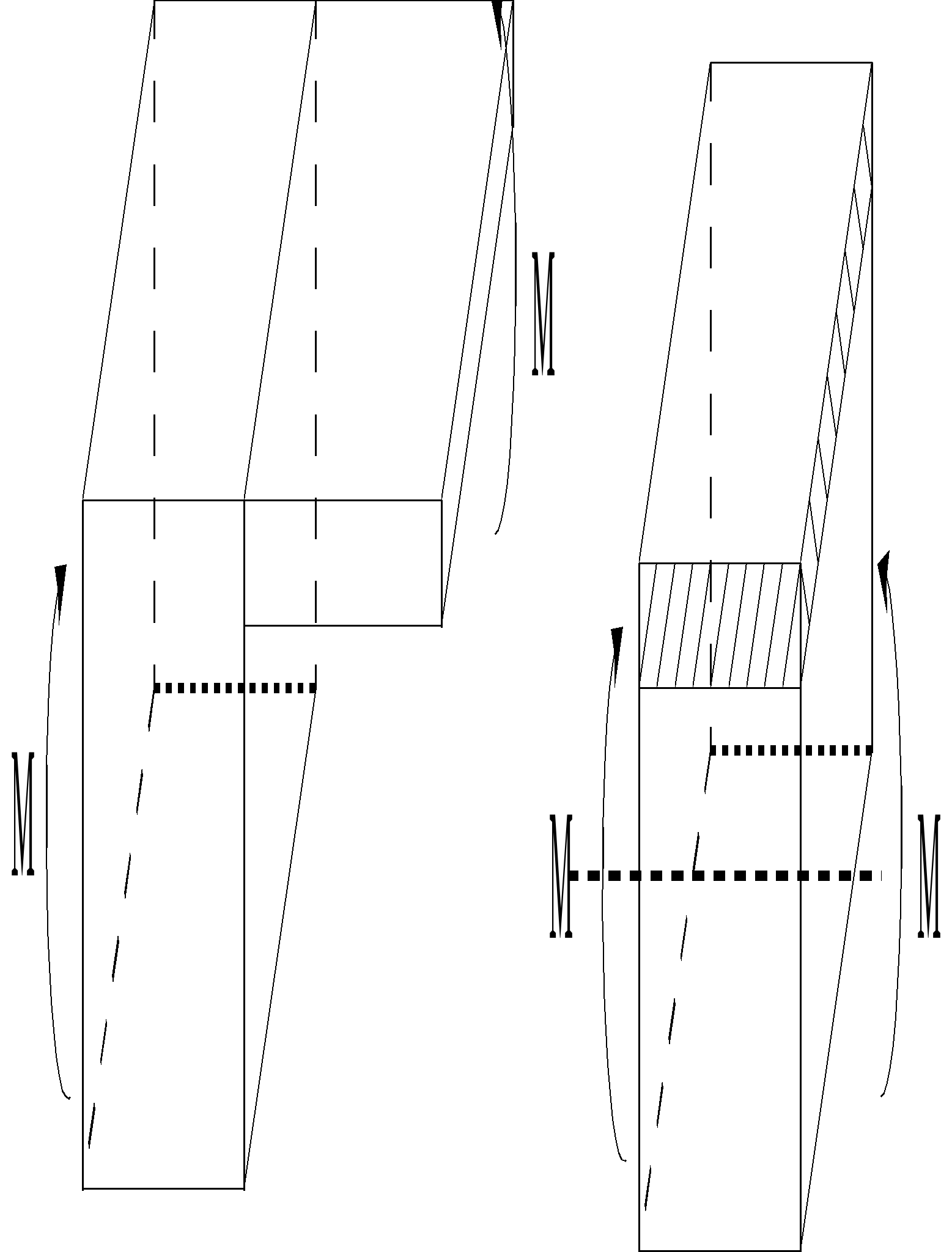
In the case of the figure on the right, the approach developed above is preferable because the expression of the loadings is defined in relation to the average sheet of each plate. In the case of the figure on the left, if it is desired to replace the multi-layer shell by two eccentric shells, the reference axis is the middle sheet of the multi-layer shell. It is therefore in the interest of defining everything in relation to the design plan. It is this approach that is adopted in the code. All applied loads are considered to be defined by default in the sketch coordinate system or mesh plane. If certain loads are defined in relation to other planes (middle sheet, upper or lower sheet) it is up to the user to make the appropriate coordinate changes, manually or through the command file, specifying the plan for applying the efforts when possible (see [§5]), to reduce to a loading defined in the mesh plane.
3.2. Work of forces and external couples#
The work of the forces and torques exerted on the plate is expressed in the following way:
\({W}_{\text{ext}}=\underset{S}{\int }\underset{d-h/2}{\overset{d+h/2}{\int }}{F}_{v}\text{.}U\text{dV}+\underset{S}{\int }{F}_{s}\text{.}U\text{dS}+\underset{C}{\int }\underset{d-h/2}{\overset{d+h/2}{\int }}{F}_{c}\text{.}U\text{dz}\text{ds}\)
where: |
\({F}_{v}\) , \({F}_{s}\) , , \({F}_{c}\) are the volume, surface and contour forces acting on the plate, respectively. \(C\) is the portion of the plate contour to which the \({F}_{c}\) contour forces are applied. |
With the [§2.2] kinematics, we determine as follows:
\(\begin{array}{c}{W}_{\text{ext}}=\underset{S}{\int }({f}_{x}u+{f}_{y}v+{f}_{z}w+{c}_{x}{\theta }_{x}+{c}_{y}{\theta }_{y})\text{dS}+\underset{C}{\int }({\phi }_{x}u+{\phi }_{y}v+{\phi }_{z}w+{\chi }_{x}{\theta }_{x}+{\chi }_{y}{\theta }_{y})\text{ds}\\ =\underset{S}{\int }({f}_{x}u+{f}_{y}v+{f}_{z}w+{c}_{y}{\beta }_{x}-{c}_{x}{\beta }_{y})\text{dS}+\underset{C}{\int }({\phi }_{x}u+{\phi }_{y}v+{\phi }_{z}w+{\chi }_{y}{\beta }_{x}-{\chi }_{x}{\beta }_{y})\text{ds}\end{array}\)
where are present on the plate:
\({f}_{x},{f}_{y},{f}_{z}\) the surface forces acting according to \(x\), \(y\) and \(z\);
\({f}_{i}=\underset{-h/2}{\overset{+h/2}{\int }}{F}_{v}\text{.}{e}_{i}\text{dz}+{F}_{s}\text{.}{e}_{i}\) where \({e}_{x}\) and \({e}_{y}\) are the base vectors of the tangential plane and \({e}_{z}\) are their normal vector;
\({c}_{x},{c}_{y}\): surface torques acting around the axes \(x\) and \(y\);
\({c}_{i}\mathrm{=}\underset{\mathrm{-}h\mathrm{/}2}{\overset{+h\mathrm{/}2}{\mathrm{\int }}}\mathrm{[}(z+d){e}_{z}\mathrm{\wedge }{F}_{v}\mathrm{]}\text{.}{e}_{i}\text{dz}+\mathrm{[}(d\mathrm{\pm }\frac{h}{2}){e}_{z}\mathrm{\wedge }{F}_{s}\mathrm{]}\text{.}{e}_{i}\) where \({e}_{x}\), \({e}_{y}\), \({e}_{z}\) are the base vectors defined previously.
and where are present on the contour of the plate:
\({\phi }_{x},{\phi }_{y},{\phi }_{z}\) the linear forces acting according to \(x\), \(y\) and \(z\);
\({\phi }_{i}\mathrm{=}\underset{\mathrm{-}h\mathrm{/}2}{\overset{+h\mathrm{/}2}{\mathrm{\int }}}{F}_{c}\text{.}{e}_{i}\text{dz}\) where \({e}_{x}\), \({e}_{y}\), \({e}_{z}\) are the base vectors defined previously;
\({\chi }_{x},{\chi }_{y}\) the linear torques around the axes \(x\) and \(y\);
\({\chi }_{i}\mathrm{=}\underset{\mathrm{-}h\mathrm{/}2}{\overset{+h\mathrm{/}2}{\mathrm{\int }}}\mathrm{[}(z+d){e}_{z}\mathrm{\wedge }{F}_{c}\mathrm{]}\text{.}{e}_{i}\text{dz}\) where \({e}_{x}\), \({e}_{y}\), \({e}_{z}\) are the base vectors defined previously.
Note:
The moments compared to \(z\) suck. The forces and torques are expressed in the mesh coordinate system. All calculations are done by default in the sketch coordinate system. If forces or torques are expressed in another coordinate system (that of the middle sheet of the plate for example) the user must do the conversions manually if using the default options or specify the plan for applying the efforts (see paragraph [§ 5 ]) .
3.3. Principle of virtual work and balance equations#
This paragraph is unchanged from paragraph [§3.3] of [R3.07.03].