4. Contents of the sd_modele_xfem objects#
4.1. General objects#
4.1.1. . MODELE_SAIN#
The concept. MODELE_SAIN is a K8 vector of length 1 containing the name of the model on which the rich model is built (value of the MODELE_IN keyword as input to MODI_MODELE_XFEM).
4.2. Contents of objects related to concatenation#
4.2.1. . LNNO,. LTNO,. BASLOC and. STNO#
Attention, these objects do not have the same structure as the objects of the same name contained in the sd_fiss_xfem ([§ 3.2.2], [§ 3.2.4] and [§ 3.3.3]). These are elementary fields of type ELNO and not CHAM_NO. The main difference is that CHAM_NO stores information on mesh nodes (one value per node) while CHAM_ELNO stores information per node on the element. Since a node is connected to \(N\) elements, the value will be stored \(N\) times. The purpose of this choice is to store information from several cracks in an element, the concept of sub-point is then used.
If an element is contained in the SD fiss (i) //”. MAILFISS. HEAV “, we say that it is seen by the crack i: the information relating to this crack must then be stored in the model. If the element sees 2 or more cracks, information about all cracks should be stored in the model. By defining the number of sub-points \(\mathit{NBSP}\) of CHAM_ELNO as the number of cracks seen by the element, we are duplicating \(\mathit{NBSP}\) times the memory space relating to the SD for the element that sees \(\mathit{NBSP}\) cracks. So we can store the information of all the cracks in this element.
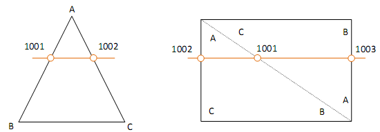
The figure shows an example of the concatenation of 2 cracks in the model. In this figure, SDs are represented. LNNO of the 2 cracks and that of the model. The element in the center sees 2 cracks, so field MODELE contains 2 components per node in this element.

Figure 4.2.1-1Example of multiple SD storage in the model.
4.2.2. . NOXFEM#
It is a 2-component CHAM_NO. The components are affected if the node has an X- FEM enrichment (i.e. there is a fiss crack (i) for which the fiss (i) field //” exists. STNO “is not zero at this node). The first component corresponds to the mesh number X- FEM containing the node. The second component is the local node number in this mesh X- FEM. This structure is useful for the imposition of Dirichlet-type boundary conditions.
4.2.3. . FISSNO#
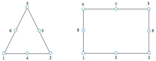
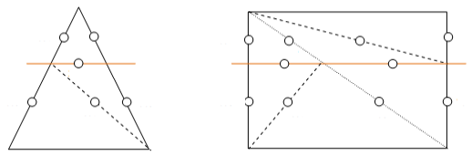
It’s a CHAM_ELNO. This SD is created when at least one element of the structure needs to store information from several cracks. For the introduction of several Heaviside degrees of freedom, the choice was made to increment the degrees of freedom numbers sequentially by nodes. For example figure, two cracks are introduced. For the first crack (in blue on the left), we assign DDL \(\mathit{H1}\). For the second crack (in red in the center) degrees of freedom \(\mathit{H1}\) are assigned to nodes that do not already have degrees of freedom \(\mathit{H1}\) affected previously, and degrees of freedom \(\mathit{H2}\) for the nodes that already have degrees of freedom \(\mathit{H1}\). This choice is made in order not to burden the elementary catalogs. Indeed, this strategy does not require an element that only has \(\mathit{H2}\).

Figure 4.2.3-1Heavisid degrees of freedom, for two cracks that overlap
However, care must be taken, because in some elements, the incrementation of the cracks does not provide a direct link between the global Heaviside degree of freedom number and the crack number (In the example, \(\mathit{H1}\) may correspond to crack 1 or crack 2 in the yellow element). When assembling in TEs, it is therefore necessary to be able to associate the degrees of freedom \({H}_{\mathit{IFH}}\mathrm{[}X,Y,Z\mathrm{]}\) (with \(\mathit{IFH}\) the global Heaviside degree of freedom number) of the node \(\mathit{INO}\) to the correct crack number. In addition, the elements must be completed by Heaviside degrees of freedom which are then eliminated (degrees of freedom in gray in the figure on the right). To eliminate degrees of freedom \({H}_{\mathit{IFH}}\mathrm{[}X,Y,Z\mathrm{]}\) from node \(\mathrm{INO}\), you must have the status of the correct crack in \(\mathit{INO}\).
The SD MODELE//”. FISSNO “allows you to do that. It returns the crack number \(\mathit{IFISS}\) seen locally at node \(\mathit{INO}\) for degrees of freedom \({H}_{\mathit{IFH}}\mathrm{[}X,Y,Z\mathrm{]}\). We have \(\mathit{IFISS}\mathrm{=}\mathit{FISSNO}(\mathit{INO},\mathit{IFH})\). We then get the right pointer for SD MODELE//”[. LNNO,. STNO. TOPOSE. HEA].

Figure 4.2.3-2 Example of constructing the SD Model. FISSNO
The figure illustrates the construction of the painting. FISSNO. The rows correspond to the node numbers, and the columns to the Heaviside degree of freedom numbers. The table is filled in sequentially in 2 passes. During the first pass, we look at the status (MODELE). STNO) from node \(\mathit{INO}\) for crack \(\mathit{IFISS}\). If the status is not zero, fill in the first box with the data \(\mathit{IFH}\) in their search order at \(\mathit{INO}\) which has not already been assigned with \(\mathit{IFISS}\). We complete the table if necessary during the second pass by proceeding as for the first pass but by filling in the boxes with the data \(\mathit{IFH}\) in \(\mathit{INO}\) if the status is zero.
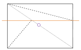
To illustrate the use of this SD, we use the simpler example in the figure on the figure. Model was then built. FISSNO for the middle element. If you want (during assembly for example) to retrieve the Heaviside function associated with node \(\mathit{N1}\) for degrees of freedom \({H}_{1}\mathrm{[}X,Y\mathrm{]}\). The crack number is retrieved via \(\mathit{IFISS}\mathrm{=}\mathit{FISSNO}(\mathit{INO}\mathrm{=}\mathrm{1,}\mathit{IFH}\mathrm{=}1)\mathrm{=}2\). We then have the Heaviside function which is worth \(\mathit{HE}(\mathit{IFISS}\mathrm{=}2)\mathrm{=}+1\). For node \(\mathit{N4}\), we will have \(\mathit{FISSNO}(\mathrm{4,1})\mathrm{=}1\) and therefore \(\mathit{HE}(\mathit{IFISS}\mathrm{=}1)\mathrm{=}\mathrm{-}1\).

Figure 4.2.3-3 Example for the SD Model. FISSNO
More generally, the Heaviside function in an integration sub-element \(\mathit{SE}\), for a node \(\mathit{INO}\) and a Heaviside degree of freedom \(\mathrm{IFH}\), is obtained in the following way:
\(\mathit{HE}(\mathit{SE},\mathit{INO},\mathit{IFH})\mathrm{=}\mathit{HE}(\mathit{SE},\mathit{IFISS}(\mathit{INO},\mathit{IFH}))\).
This data structure also makes it possible to remove excess Heaviside degrees of freedom in \(\mathit{TE}\). We get the status back (MODELE). STNO) from node \(\mathit{INO}\) for Heaviside degree of freedom \(\mathit{IFH}\), while this structure is stored by crack:
\(\mathit{STATUT}(\mathit{INO},\mathit{IFH})\mathrm{=}\mathit{STATUT}(\mathit{INO},\mathit{IFISS}(\mathit{INO},\mathit{IFH}))\).
This structure is also used for X- FEM post-treatment, during the interpolation of movements on the lips of the crack.
4.2.4. . HEAVNO#
It is the inverse structure of. FISSNO. This SD is created when at least one element of the structure needs to store information from several cracks. It is being built at the same time as. FISSNO and returns the Heaviside degree of freedom number associated with node \(\mathrm{INO}\) and crack \(\mathrm{IFISS}\). Keeping the notations from the previous paragraph we have:
\(\mathrm{IFH}=\mathrm{HEAVNO}(\mathrm{INO},\mathrm{IFISS})\)
In the case of multi-Heaviside contact, the Lagrange degree of freedom number associated with a crack \(\mathrm{IFISS}\) corresponds to the corresponding Heaviside degree of freedom number \(\mathrm{IFH}\). Thus, this data structure makes it possible to find the name of the Lagrange degree of freedom (and its position in the elementary matrix/vector) from the crack number. If we treat contact on a contact facet associated with crack \(\mathrm{IFISS}\), the Lagrangian who works at node \(\mathrm{INO}\) has the number:
\(\mathrm{ILAG}=\mathrm{HEAVNO}(\mathrm{INO},\mathrm{IFISS})\)
4.3. Contents of sub-element topology objects#
Developer notes:
some \(\mathit{ma}\) values are hard-coded in Fortran (te0514, xbsigm, xmel3d…)
a maximum of 4 cracks is allowed for multi-heaviside models
the lengths of the data structures are therefore multiplied by 4 from mono-heaviside to multi-heaviside
Reminder on how the X- FEM elements are divided (Document R7.02.12 part 3.3 Sub-division):
3D |
2D |
|||
Cutting (1) Preliminary cutting phase |
Each element (hexahedron, pentahedron) is virtually cut into tetrahedra |
Each element (hexahedron, pentahedron) is virtually cut into tetrahedra 6 tetrahedra at most |
Each element (quadrangle) is virtually divided into triangles |
Each element (quadrangle) 2 triangles at most |
Cutting (2) Sub-division |
Each tetrahedron is in turn divided into sub-tetrahedra 6 subtetrahedra at most |
Each triangle is in turn divided into sub-triangles 3 sub-triangles at most |
||
Points of intersection |
Points of intersection between the edges of the tetrahedra resulting from the cut (1) and the surface of the crack Maximum 11 intersection points |
Points of intersection between the edges of the triangles resulting from the cut (1) and the crack curve Maximum 3 intersection points |
||
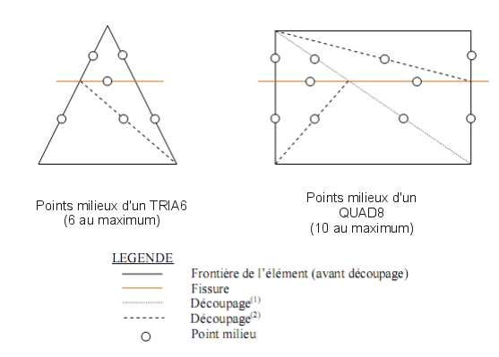
Midpoints |
Points in the middle of the edges of the triangles resulting from the cut (2) [provided that they do not coincide with any node of the complete initial element] 66 points at most (59 midpoints at most distinct from the central nodes and 7 central points at most) |
Points in the middle of the edges of the triangles resulting from the cut (2) [provided that they do not coincide with any node of the initial element] 11 midpoints at most (10 midpoints at most distinct from the central nodes and 1 central point at most) |
||
Central point of the quadratic quadrangle |
Storing the midpoints of the quadratic faces of the quadratic polyhedron. Maximum 7 center points |
Intersection point of the two right diagonals of a quadratic quadratic quadrangle 1 central point at most |
||
Cutting process (1) and sub-cutting (2) |
1 element X- FEM 3D (2) tetrahedron No. 1 max. 6 subtetrahedra Tetrahedron No. 2 max. 6 subtetrahedra … |
1 element X- FEM 2D (2) triangle no. 1 3 sub-triangles at max. Triangle #2 3 sub-triangles at most. |
Note: the number of sub-elements is not changed by the introduction of square cells.
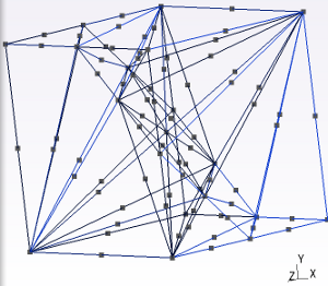
Figure 4.3-1: configuration generating the maximum number of intersection points/midpoints
4.3.1. . TOPOSE. PIN#
Learn about the INtersection Points.
It is a constant field per element (CHAM_ELEM) with 33 real components.
For each element, this field contains the coordinates of the intersection points (in the sense defined above). Since the maximum number of such points is 11, and since we work in dimension 3, the number of components per element is dimensioned at 33. For each element, the components are ordered like this:
where
are the coordinates of the \(i\) th intersection point on the element.
It should be noted that if the element is not cracked, the components are zero.
In 2D, we have a maximum of 3 intersection points of instincts, nodes, vertices, with 2 components each, so 6 components in total.
For the multiheaviside:
In 3D, the field requires \(33\times 4=132\) real components.
In 2D, the field requires \(6\times 4=24\) real components.
4.3.2. . TOPOSE. PMI#
Provides information on midpoints in the presence of quadratic cells.
4.3.2.1. . 2D#
It is a constant field per element (CHAM_ELEM) with 22 real components. For each element, this field includes:
the coordinates of the midpoints
Note: remember that the coordinates of midpoints that coincide with a node of the parent element are not stored in this data structure.
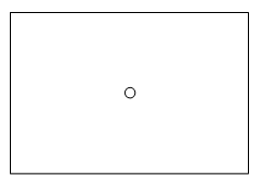
Figure 4.3.2.1-1: Center point of a QUAD8 (1 maximum) - the coordinates of the central point introduced during the division (1) of a QUAD8:
That’s a total of 11 points at most. Since we are using 2D, we can have a maximum of \(11\times 2=22\) components. The field is thus dimensioned to 22.
For each element, the components are ordered like this:
\(\{{x}_{1},{y}_{1},{x}_{2},{y}_{2},\mathrm{...},{x}_{11},{y}_{11}\}\)
where \({({x}_{i},{y}_{i})}_{1\le i\le 10}\) are the coordinates of the \(i\) th midpoint on the element and where \(({x}_{11},{y}_{11})\) are the coordinates of the center node of a QUAD8.
4.3.2.2. . 3D#
It is a constant field per element (CHAM_ELEM) with 198 real components. For each element, this field includes:
the coordinates of the midpoints (66 points maximum),
the coordinates of the center points introduced when cutting the 3D quadratic element (a maximum of 7 additional center points, for example, when slicing a HEXA20 via the complete element HEXA27).
For each element, the components are ordered like this:
\(\{{x}_{1},{y}_{1},{z}_{1},{x}_{2},{y}_{2},{z}_{2},\mathrm{...},{x}_{65},{y}_{65},{z}_{65}\}\)
4.3.3. . TOPOSE. CNS#
Provides information on sub-element connectivity.
4.3.3.1. . 3D#
It is a constant field per element (CHAM_ELEM) with 320 integer components. This field is sized in relation to the sub-division of the quadratic elements in TETRA10. For linear sub-division, it is therefore oversized, with no significant impact on computation and performance.
For each element, this field contains the connectivity of the sub-elements of the element. By convention, all sub-elements are 10-node tetrahedra (TETRA10), and there can be a maximum of 32 sub-elements per X- FEM element (for a detailed explanation of this result, see the reference documentation on the X- FEM [R7.02.12] method). There are a maximum of 6 tetrahedra and 6 sub-elements per tetrahedron, but there is no configuration with 6 sub-elements for each tetrahedron, which is why the maximum is 32. The components are arranged 4 by 4. The object. TOPOSE. CNS refers to 3 types of nodes: either already existing nodes in the mesh, or intersection points, or middle nodes. So, for each element:
if a vertex of a sub-element is a node of the X- FEM element in question, then this node is identified by its local number in the element;
if a vertex is an intersection point, then this point is identified by a number greater than 1000, where the unit number refers to its local number in the list of intersection points of the element.
concerning the middle nodes: if the middle node is a node of the parent element, the local number of the node is stored in the parent element; if it is a new middle node generated by the cut, the point is then identified by a number greater than 2000. If the midpoint is also a central point of the parent element, it is then identified by a number greater than 3000.
Example:
For the ie element:
CNS (ie) =
1001 |
1005 |
6 |
1002 |
1002 |
1002 |
2001 |
2005 |
3021 |
2004 |
1003 |
1003 |
6 |
6 |
… |
1st subtetra: node 1:1001 -> refers to the 1st point of PIN (ie)
node #2:1005 -> refers to the 5th point of PIN (ie)
node #3:6 -> returns to the 6th node of the ie element
node #4:1002 -> refers to the 2nd point of PIN (ie)
node #5:2001 -> refers to the 1st point of MIL (ie)
node 6:12 -> returns to the 12th node of the ie element
node #7:2005 -> refers to the 5th point of MIL (ie)
node #8:3012 -> refers to the 12th point of MIL (ie)
node 9:6 -> returns to the 6th node of the ie element
node #10:3021 -> refers to the 21st point of MIL (ie)
2nd subtetra: vertex 1:1003 -> refers to the 3rd point of PIN (ie)
vertex #2:6 -> returns to the 6th node of the ie element
…
4.3.3.2. . 2D#
It is a constant field per element (CHAM_ELEM) with 36 integer components. This field is sized in relation to the sub-division of the quadratic elements in TRIA6.
For each element, it contains the connectivity of the sub-elements of the element.
We count:
6 sub-triangles maximum (achieved for a quadrangle mesh)
6 knots maximum for each sub-triangle (achieved for a quadratic mesh)
That makes \(6\times 6=36\) components at most. The field is therefore dimensioned to 36 and the latter are arranged 6 by 6.

The object. TOPOSE. CNS refers to 4 types of points:
Type 1: Element node (belonging to the mesh)
It is identified by its local number in the element
Type 2: Intersection point
It is identified by a number \(1000+u\), where \(u\) refers to its local number in the element’s list of intersection points.
100 1 → 1st point stored in PINTTO
1002 → 2nd point stored in PINTTO…
Type 3: Midpoint
It is identified by a number \(2000+u\), where \(u\) refers to its local number in the element’s list of midpoints.
200 1 → 1st point stored in PMILTO
200 2 → 2nd point stored in PMILTO, etc.
Type 4: Quadrangle midpoint
It is identified by a number \(3000+u\), where \(u\) refers to its local number in the element’s list of midpoints.
3011
30 11 → 11th point stored in PMILTO
4.3.3.3. . Multiheaviside case#
For multiheaviside models, only linear sub-division is allowed. We then use the dimensions of the linear division connectivity tables (3D: TETRA4 instead of TETRA10/2D: TRIA3 instead of TRIA6).
The dimensions of the monoheaviside connectivity tables are then multiplied by the maximum number of cracks:
In 3D, \(128\times 4=512\) integer components.
In 2D, \(18\times 4=72\) integer components.
4.3.4. . TOPOSE. HEA#
Tell me about the value of the HEAviside function.
It is a constant CHAM_ELEM per sub-element with 32 integer components corresponding to the value of the Heaviside function on the subtetrahedra (+1 or —1), arranged in succession.
There may be 0s if the total number of sub-elements is < 32 (max number of sub-tetrahedra).
In 2D, there are a maximum of 6 sub-elements, field TOPOSE. So HEA is sized to 6.
If the element sees several cracks, this field is duplicated as many times as there are cracks. We then use the number of sub-points \(\mathit{NBSP}\) defined in [§ 4.2.1]. The field will have \(32\times \mathit{NBSP}\) components in 3D and \(6\mathrm{\times }\mathit{NBSP}\) components in 2D.
4.3.5. . TOPOSE. LON#
Indicates the value of the LONgueur of fields used to define the sub-elements.
It is a constant field per element (CHAM_ELEM) with one integer component, in 2D as in 3D. This component corresponds to the number of sub-elements contained in the X- FEM element.
4.3.6. . TOPOSE. PAI#
Learn about intersecting edges. This data structure is passed to option TOPOFA so that it is not recalculated to generate the data structure. TOPOFAC .AI
Its structure is similar to. TOPOFAC .AI:
It is a constant field per element (CHAM_ELEM) with 15 or 55 real components containing information about intersected edges.
For each of the intersection points of each element:
The 1st component is the local number of the corresponding edge (0 if it is a vertex node).
The 2nd component is the local number of the node if it is a vertex node (0 otherwise).
The 3rd component is the length of the edge.
The 4th component is the position of the intersection point on the edge, with an arbitrary direction that depends on the mesh. This real is strictly between 0 and 1, and is equal to 0 if the intersection point is a vertex node.
The 5th component makes it possible to know if the intersected edge is vital or not. If it is vital, the component is 1, if it is not, the component is equal to 0.
The number of components per intersection point (5) is accessible in Fortran by a call to function XXMMVD (“ZXAIN”)
Let \((n,{\tau }_{1})\) be the \((n,{\tau }_{\mathrm{1,}}{\tau }_{2})\) th element of the mesh,
V =. TOPOFAC .AI (i); |
|
V (1) |
Local number of the edge corresponding to the first intersection point |
V (2) |
Local number of the node corresponding to the 1st intersection point |
V (3) |
Length of the edge corresponding to the 1st intersection point |
V (4) |
Position of the 1st intersection point on the edge |
V (5) |
1st intersection point: if on vital edge (1) otherwise (0) |
V (6) |
Local number of the edge corresponding to the 2nd intersection point |
… |
… |
V (55) |
11th point of vital intersection (1) or not (0) |
If the number of intersection points is strictly less than the maximum number of intersection points (3 or 11 depending on the case), the vector is completed by 0s.
In 2D, we have a maximum of 3 points with 5 pieces of information in the same way as in 3D (edge number, node number, length of the edge and position of the intersection point, intersected edge vital or not). Field TOPOFAC. AIa so 15 components per element. In 3D we have 55 components.
4.3.7. . TOPOSE. PJO#
This SD is only used for cohesive Multi-Heaviside HM- XFEM elements. This is a CHAM_ELEM. which has one integer component per element node. So it has up to 20 components. This component is 0 if the node does not contain a crack junction on its support and 1 otherwise. This information is then used to impose the continuity of the fluid pressure in the interface branches at the level of a hydraulic crack junction (confer [R7.02.18]).
4.5. Objects relating to the definition of characteristic domain functions#
4.5.1. TOPONO. HNO#
This field ELNO contains the « integer » codes representing the domain ID numbers per node and per element. Each Heaviside enriched node can represent up to a maximum of 4 cracks per element. It is shown incrementally that 4 cracks/junctions define a maximum of 5 domains per element.
So to describe the environment of each node X- FEM (Heaviside), we therefore allocate 5 locations per node and per element, in the \(\text{TOPONO.HNO(NNO*5)}\) array, filled in the following way:
V =. TOPONO. HNO (i); |
|
V (1) |
Integer code representing the 1st domain seen by the 1st node of the element |
V (2) |
Integer code representing the 2nd domain seen by the 1st node of the element |
V (3) |
Integer code representing the 3rd domain seen by the 1st node of the element |
V (4) |
Integer code representing the 4th domain seen by the 1st node of the element |
V (5) |
Integer code representing the 5th domain seen by the 1st node of the element |
V (6) |
Integer code representing the 1st domain seen by the 1st node of the element |
V (7) |
Integer code representing the 2nd domain seen by the 2nd node of the element |
V (8) |
Integer code representing the 3rd domain seen by the 2nd node of the element |
V (9) |
Integer code representing the 4th domain seen by the 2nd node of the element |
V (10) |
Integer code representing the 5th domain seen by the 2nd node of the element |
… |
… |
V (5*N) |
Integer code representing the 5th domain seen by the Nem/element node |
Moreover, concerning the organization of the storage of the 5 domains seen by each node: the first 4 locations are reserved for the « complementary » domains of the domain to which the node belongs, the last location is reserved for the domain to which the node belongs.
When the crack passes through the node, the domain to which the node belongs is selected automatically using the « sign » function. By convention we have: \(\mathit{He}(\mathit{lsn}=0)=\mathit{sign}(0)=1\). This convention makes it possible to extend the coding of domains on the edge of the elements and therefore at the nodes by continuity.
Recall that domain coding is done by base-4 projection of Heaviside sign functions at the current P point (either a node or a gauss point):
\(\mathit{code}(\underline{P})=\sum _{\mathit{ifiss}=1}^{\mathit{nfiss}}{4}^{\mathit{nfiss}-\mathit{ifiss}}\left(\mathit{He}(\underline{P},\mathit{ifiss})+2\right)\)
Using SDs \(\text{.LNNO}\) and \(\text{.TOPOSE.HEA}\), for each « Heaviside » node, we then calculate the code of the domain to which the node belongs and the code of the domains seen by the node (partitioned in the sub-elements).
Moreover, given the local construction of the concatenated field \(\text{.LNNO}\), the same domain can have several codes from one element to another, because a node can see a different number of cracks from one element to another (see figure). This poses a significant challenge in the organization of field TOPONO. HNO so that the coding keeps a non-local meaning, in other words, so that the information \(\text{TOPONO.HNO(jno,i)}\) always represents the intersection of the support of node no. \(\text{jno}\), with the domain \({\Omega }_{\text{i}}\) regardless of the element considered.
To get around this difficulty, we define polymorphic domains instead. In other words, the same domain may have a different code from one Heaviside element to another. Therefore, the code \(\text{TOPONO.HNO(jno,i)}\) represents the intersection of the support of node \(\text{jno}\) with a domain \({\Omega }_{\text{i}}\), « seen from the current element ».
This « elementary » construction is then in line with all elementary calculations, including for late meshes [R5.03.53].
4.5.2. TOPONO. HSE#
This basic field contains one « integer » code per sub-element X- FEM. Its sizing is then based on the number of sub-elements resulting from the sub-division cf. \(\text{TOPOSE.LON}\).
This SD represents the coding of the Heaviside sign field by sub-element \(\text{.TOPOSE.HEA}\). It allows the calculation of characteristic domain functions at volume Gauss points.
Indeed, each Gauss point XFEM is located in a sub-element. The sub-element is itself a sub-partition of a domain. Assigning one code per sub-element is then sufficient to characterize all domain partitions on the current element.
We then allocate as many integer locations as there are sub-elements in the current element \(\text{TOPONO.HSE(NSE)}\).
V =. TOPONO. HSE (i); |
|
V (1) |
Integer code representing the domain partition to which the 1st sub-element belongs |
V (2) |
Integer code representing the domain partition to which the 2nd subelement belongs |
V (3) |
Integer code representing the domain partition to which the 3rd subelement belongs |
… |
… |
V (N) |
Integer code representing the domain partition to which the Nth Sub-element belongs |
4.5.3. TOPONO. HFA#
This elementary field contains 2 « integer » codes per sub-facet X- FEM. The first code represents the slave domain. The second code represents the master domain.
These two codes are calculated using the same coding formula as the SDs. » TOPONO » previous ones. In contrast, the coding here is based on the Heaviside \(\text{TOPOFAC.HE}\) sign field. As this last field is only present in Multi-Heaviside, field \(\text{TOPONO.HFA}\) is only created in Multi-Heaviside. Extending this field in Mono-HeavisisDE does not present any major difficulty and would improve the readability of the code. For the moment, in this case, the code \(\text{TOPONO.HFA}\) is calculated from the sign of the Heaviside function on either side of the facet, i.e. ±1.
The dimensioning of field \(\text{TOPONO.HFA}\) is then based on the number of sub-facets resulting from the sub-division (cf. \(\text{TOPOFAC.LO}\)) and on the number of cracks seen by the element, since a sub-facet is a partitioning of a crack within the current element.
We then have:
V =. TOPONO. HFA (i); |
|
V (2*nface* (ifiss-1) +2*ifa-1) |
Domain code on the slave side of the ifiss crack of the subfacet number ifa |
V (2*nface* (ifiss-1) +2*ifa) |
Domain code on the master side of the ifiss crack of the subfacet no. ifa |
4.6. Other objects#
4.6.1. . XFEM_CONT#
Vector of integers with a length equal to 1. This value is equal to:
0 if there is no contact;
1 if a contact relationship or a cohesive relationship has been defined between the lips of the crack, and linear finite elements are used with a standard formulation for contact (CONTACT =” STANDARD “in MODI_MODELE_XFEM);
2 if a contact relationship or a cohesive relationship has been defined between the lips of the crack, and linear elements are used with a « mortar » formulation for contact (CONTACT =” MORTAR “in MODI_MODELE_XFEM);
3 if a contact relationship or a cohesive relationship has been defined between the lips of the crack, and quadratic elements are used with a standard formulation for contact.
4.6.2. . NFIS#
Vector of integers with a length equal to 1. It corresponds to the number of cracks X- FEM in the model.
4.6.3. . FISS#
K8 vector with a length equal to the number of cracks X- FEM in the model. It corresponds to the name of the sd_fiss_xfem for each crack.
4.6.4. . XMAFIS#
CHAM_ELEM by K8. For each mesh, this CHAM_ELEM corresponds to the name of the cracks seen by this mesh, in the order defined by the user. The number of sub-points in this SD corresponds to the number of cracks seen by the mesh.
4.6.5. . PRE_COND#
Character string length 8 [K8]. For each model XFEM, it provides information on the activation of algebraic pre-conditioning XFEM. This pre-conditioning is essential with quadratic elements.