1. Reference problem#
1.1. Geometry#
The geometry (generated automatically in the macro command SIMU_POINT_MAT [U4.51.12]) is unique and simple: in \(\mathrm{3D}\) it is a tetrahedron with side 1, and in \(\mathrm{2D}\) it is a triangle with side 1, at whose nodes linear relationships are applied to obtain a state of homogeneous stress and deformation.
1.2. Material properties#
Material characteristics are defined for each behavior using the DEFI_MATERIAU command. The elastic characteristics and the elastic limit selected are those of standard 16 MND5 steel:
\(E=200000\mathrm{MPa}\), \(\nu =0.3\), \({\sigma }_{y}=437\mathrm{MPa.}\)
The other parameters describing the laws were chosen from Code_Aster test cases. The following two tables summarize all the Code_Aster laws considered and the associated parameters
Model. |
viscoplastic laws of ASTER |
parameters retained |
test selected for the choice of parameters |
A |
LEMAITRE |
m = 5.6

Kinv=1/K= 3.2841e-4

n = 11
|
Test ASTER SSNA01A |
B |
VISC_CIN1_CHAB |
    SY = 437.0;

    Rinf = 758.0;

    b = 2.3;

    Cinf = 63767.0

    Gamma0 = 341.0

1/m = 0
Kinv=1/K= 3.2841e-4

.. code::

    n = 11
|
work hardening: data 16 MND5 other parameters: ssnv101c |
C |
VISC_CIN2_CHAB |
SY = 437.0;

Rinf = 758.0;

b = 2.3;

C1inf = 63767.0/2.0

C2inf = 63767.0/2.0

Gam1 = 341.0

Gam2 = 341.0

1/m = 0

1/K= 3.2841e-4

n = 11
|
Crouching data 16 MND5 other parameters ssnv101c
|
D |
VISC_ENDO_LEMA |
SY=0.0

N=12.0

UN_SUR_M=1/9.0

UN_SUR_K=1/2110.0

R_D=6.3

A_D=3191.0
|
|
E |
VISC_TAHERI |
SY = 437.0; Sinf = 758.0;

alpha = 0.3;

m = 0.1;

a = 312.0;

b = 30.0;

c1 = -0.012;

cinf = 0.065
|
Test ASTER SSNP101B |
F |
VISC_ISOT_LINE |
SY=437 MPa, DSY =2024 Mpa
|
SSNL129 test for part VISC_SINH
|
G |
VISC_ISOT_TRAC |
tensile curve at 100°C of 16 MND5
|
SSNL129 test for part VISC_SINH
|
H |
VISC_CIN2_MEMO |
R0=SY = 437.0;

Q0 = 758.0-437.0;

Qm=Q0+100

Mu=10

Eta=0.5

b = 2.3;

C1inf = 63767.0/2.0

C2inf = 63767.0/2.0

Gam1 = 341.0

Gam2 = 341.0

1/m =0

1/K= 3.2841e-4

n = 11
|
Cinematic choice X1+X2= Xde VMIS_CIN1_CHAB.
|
I |
VISCOCHAB |
SY = 437.0;

Rinf = 758.0;

b = 2.3;

C1inf = 63767.0/2.0

C2inf = 63767.0/2.0

Gam1 = 341.0

Gam2 = 341.0

1/m = 0

1/K= 3.2841e-4

n = 11

Q0 = 758.0-437.0;

Qm=Q0+100

Mu=10

Eta=0.5
|
Work harden:Data 16 MND5 other parameters ssnv101c
|
J |
MONOCRISTAL |
viscoplastic laws of ASTER |
Plastic parameters from SSNV171.Orthotropic parameters from SSLV120 |
K |
VMIS_JOHN_COOK
|
YOUNG = 124000.e6; |
|
L |
HAYHURST
|
YOUNG = 145000. ;
|
|
1.3. Boundary conditions and loads#
1.3.1. Characteristics of loading paths#
Two loading paths have been defined to deal with cases \(\mathrm{3D}\) and \(\mathrm{2D}\) plan. They are common to all laws of behavior. Each of them meets the following criteria:
an accumulated plastic deformation, \(p\), from 4 to \(\text{5\%}\) over the entire path,
an increase of \(1\text{\%}\) in the cumulative plastic deformation \(p\) during a portion of the trip,
in the presence of viscosity, a deformation stress rate of 10-3, 10-4 and \({10}^{-5}{\text{s}}^{-1}\) respectively. These were evaluated approximately by considering an equivalent deformation of \(5\text{\%}\) over the entire journey: i.e. travel times of 50, 500 and 5000 seconds respectively for \(\text{v1}\), \(\text{v2}\) and \(\text{v3}\). The tests returned correspond to a speed of \({10}^{-5}{\text{s}}^{-1}\).
This calibration was carried out on law VMIS_ISOT_LINE, then carried over to the other laws.
The proposed loading causes each component of the deformation tensor to vary in a decoupled manner by successive step. A cyclic load-discharge path is proposed by covering the states of traction and compression as well as an inversion of the signs of shear in order to test a wide range of values.
Schematically, it follows a course on 8 segments \(\text{[O-A-B-C-O-C’-B’-A’-O]}\) where the second part of the path \(\text{[O-C’-B’-A’-O]}\) is symmetric with respect to the origin of the first \(\text{[O-A-B-C-O]}\).
1.3.2. Application of requests#
We come back to the study of a material point (using the macro-command SIMU_POINT_MAT [U4.51.12]) by soliciting an element in a homogeneous manner by imposing:
in \(\mathrm{3D}\), the 6 components of the deformation tensor:
\(\stackrel{ˉ}{\varepsilon }=\left[\begin{array}{ccc}{\varepsilon }_{\mathrm{xx}}& {\varepsilon }_{\mathrm{xy}}& {\varepsilon }_{\mathrm{xz}}\\ {\varepsilon }_{\mathrm{xy}}& {\varepsilon }_{\mathrm{yy}}& {\varepsilon }_{\mathrm{yz}}\\ {\varepsilon }_{\mathrm{xz}}& {\varepsilon }_{\mathrm{yz}}& {\varepsilon }_{\mathrm{zz}}\end{array}\right]\)
in \(\mathrm{2D}\) the three components of the tensor
\(\stackrel{ˉ}{\varepsilon }=\left[\begin{array}{cc}{\varepsilon }_{\mathrm{xx}}& {\varepsilon }_{\mathrm{xy}}\\ {\varepsilon }_{\mathrm{xy}}& {\varepsilon }_{\mathrm{yy}}\end{array}\right]\)
For a more general description, the imposed deformation tensor will be decomposed into a hydrostatic and deviatoric part on shear bases:
\(\stackrel{ˉ}{\varepsilon }=\left[\begin{array}{cc}{\varepsilon }_{\mathrm{xx}}& {\varepsilon }_{\mathrm{xy}}\\ {\varepsilon }_{\mathrm{xy}}& {\varepsilon }_{\mathrm{yy}}\end{array}\right]=p\left[\begin{array}{cc}1& 0\\ 0& 1\end{array}\right]+d\left[\begin{array}{cc}1& 0\\ 0& -1\end{array}\right]+{\varepsilon }_{\mathrm{xy}}\left[\begin{array}{cc}0& 1\\ 1& 0\end{array}\right]\) in \(\mathrm{2D}\),
\(\stackrel{ˉ}{\varepsilon }=\left[\begin{array}{ccc}{\varepsilon }_{\mathrm{xx}}& {\varepsilon }_{\mathrm{xy}}& {\varepsilon }_{\mathrm{xz}}\\ {\varepsilon }_{\mathrm{xy}}& {\varepsilon }_{\mathrm{yy}}& {\varepsilon }_{\mathrm{yz}}\\ {\varepsilon }_{\mathrm{xz}}& {\varepsilon }_{\mathrm{yz}}& {\varepsilon }_{\mathrm{zz}}\end{array}\right]=p\left[\begin{array}{ccc}1& 0& 0\\ 0& 1& 0\\ 0& 0& 1\end{array}\right]+{d}_{1}\left[\begin{array}{ccc}1& 0& 0\\ 0& -1& 0\\ 0& 0& 0\end{array}\right]+{d}_{2}\left[\begin{array}{ccc}0& 0& 0\\ 0& 1& 0\\ 0& 0& -1\end{array}\right]+\left[\begin{array}{ccc}0& {\varepsilon }_{\mathrm{xy}}& {\varepsilon }_{\mathrm{xz}}\\ {\varepsilon }_{\mathrm{xy}}& 0& {\varepsilon }_{\mathrm{yz}}\\ {\varepsilon }_{\mathrm{xz}}& {\varepsilon }_{\mathrm{yz}}& 0\end{array}\right]\) in 3D.
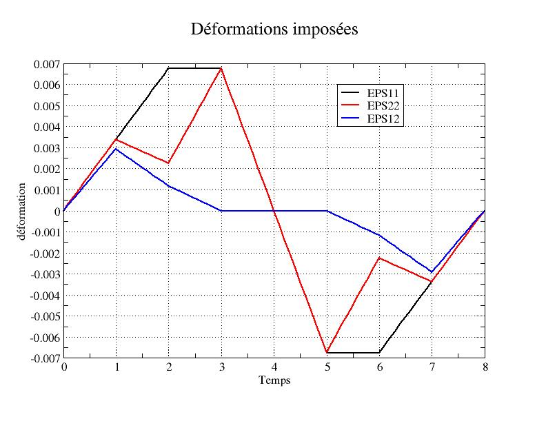
1.3.3. Description of the imposed deformation path in 2D#
The path applied is described in the table below, the deformation values are calibrated with respect to the elastic modulus:
time |
1 |
2 |
3 |
3 |
3 |
4 |
5 |
6 |
7 |
8 |
Charging point |
\(A\) |
|
|
|
|
|
|
|
||
\(E\mathrm{.}{\varepsilon }_{\mathrm{xx}}\) |
675 |
1350 |
1350 |
1350 |
0 |
-1350 |
-1350 |
-675 |
0 |
|
\(E\mathrm{.}{\varepsilon }_{\mathrm{yy}}\) |
675 |
450 |
450 |
1350 |
1350 |
0 |
-1350 |
-450 |
-675 |
0 |
\(\frac{E}{(1+\nu )}{\varepsilon }_{\mathrm{xy}}\) |
450 |
180 |
180 |
0 |
0 |
0 |
-180 |
-450 |
0 |
|
\(p\) |
675 |
900 |
900 |
1350 |
-1350 |
-900 |
-675 |
0 |
||
\(d\) |
0 |
0 |
0 |
450 |
450 |
0 |
0 |
0 |
This path is illustrated by the following graph:
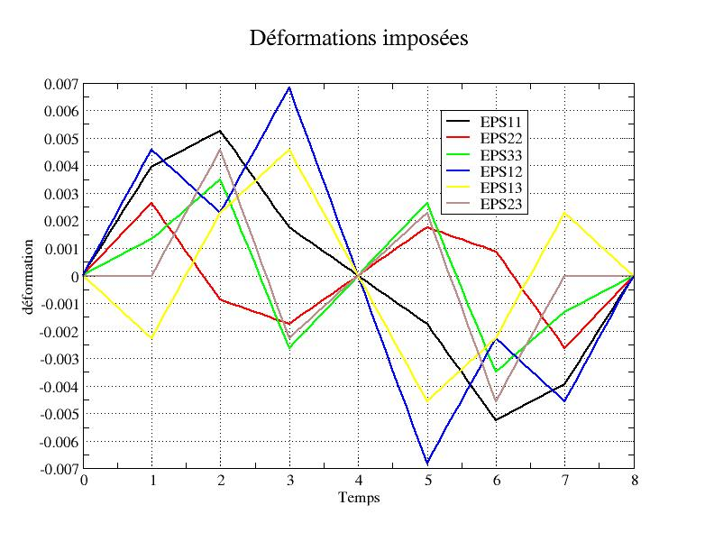
1.3.4. Description of the imposed deformation path in 3D#
The path applied is described in the table below, the deformation values applied are calibrated with respect to the elastic modulus:
Segment number |
1 |
2 |
2 |
3 |
3 |
3 |
4 |
5 |
6 |
7 |
8 |
Segment |
\(0-A\) |
|
|
|
|
|
|
|
|||
\(E\mathrm{.}{\varepsilon }_{\mathrm{xx}}\) |
787.5 |
1050 |
1050 |
350 |
350 |
0 |
-350 |
-1050 |
-787.5 |
0 |
|
\(E\mathrm{.}{\varepsilon }_{\mathrm{yy}}\) |
525.0 |
-175 |
-175 |
-350 |
-350 |
175 |
525 |
0 |
|||
\(E\mathrm{.}{\varepsilon }_{\mathrm{zz}}\) |
262.5 |
700 |
700 |
-525 |
-525 |
525 |
-700 |
-262.5 |
0 |
||
\(\frac{E}{(1+\nu )}{\varepsilon }_{\mathrm{xy}}\) |
700 |
350 |
350 |
1050 |
1050 |
-1050 |
-350 |
-700 |
0 |
||
\(\frac{E}{(1+\nu )}{\varepsilon }_{\mathrm{xz}}\) |
-350 |
350 |
350 |
700 |
700 |
0 |
-700 |
700 |
0 |
||
\(\frac{E}{(1+\nu )}{\varepsilon }_{\mathrm{yz}}\) |
0 |
700 |
-350 |
-350 |
0 |
350 |
-700 |
0 |
0 |
||
\(p\) |
525 |
525 |
525 |
-175 |
-175 |
-525 |
-525 |
0 |
|||
\({d}_{1}\) |
262.5 |
525 |
525 |
525 |
0 |
-525 |
-525 |
-262.5 |
0 |
||
\({d}_{2}\) |
262.5 |
-175 |
-175 |
350 |
350 |
0 |
-350 |
175 |
-262.5 |
0 |
This path is illustrated by the following graph:
1.4. Initial conditions#
Zero stresses and deformations.