1. Reference problem#
Since the validation of distributed reinforcements is the main object of this document, creep and RGI will not be considered here (Nullity of swelling parameters, important values of characteristic creep times).
In order to constitute a validation case, this study focuses on the stress on a reinforced concrete cube with a reinforcement density of \({\rho }^{r}=\mathrm{1,0}\text{\%}\). The cube is loaded in its armed direction (according to \(\vec{x}\)), first in tension and then in compression. In addition, in order to define a complete validation process, the study is also being relaunched for a case using 5 reinforcement densities, the maximum number of reinforcement densities that can be considered. The latter is reinforced in the same quantity (\({\rho }^{r}=\mathrm{1,0}\text{\%}\)) in the three orthogonal directions and also has two prestressed densities (\({\sigma }_{0}^{r}=\mathrm{0,1}\mathit{MPa}\)) in the vertical and horizontal direction (along \(\vec{z}\) and along \(\vec{x}\)).
1.1. Geometry#
The test is based on a unit cubic finite element with 8 knots and a side of 0.1 m.
1.2. Property of the materials#
Parameter ELAS used:
Young’s module: \(E=40000\mathit{MPa}\)
Poisson’s ratio: \(\nu =\mathrm{0,2}\)
Parameters RGI_BETON_ BA*used:*
Table 1: Values of the mechanical parameters used
RT=3.7 MPa |
EPT = 1, 0e-4 |
RC=25. MPa |
EPC =1, 0e-3 |
DELT =1. |
BETA =0.15 |
REF =4. MPa |
EKDC =1.0 e-3 |
GFT =100e-6 |
GFR =100 e-6 |
YOR = 200,000 MPa |
SYR = 400 MPa |
HPL = 1,000 MPa |
1.3. Boundary conditions#
The perpendicular displacements along three faces of the cube are blocked in order to represent the symmetry conditions and to model a simple stress case. On the lateral free face oriented along \(\vec{x}\), a DX displacement is imposed. These boundary conditions are presented on the.
Figure 1: Meshing and boundary conditions
Regarding the imposed load, it consists of a tensile load cycle followed by a compression load cycle. The evolution of this is presented below ().
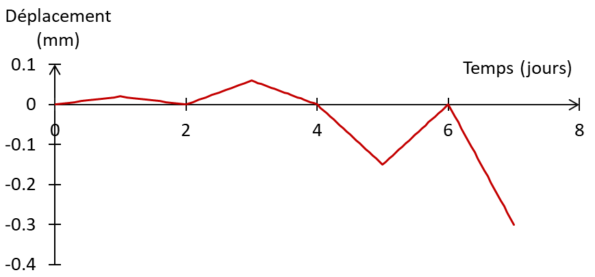
Figure 2: Imposed loading