1. Reference problem#
1.1. Geometry#
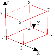
Figure 1.1-a : Geometry of the problem, cube with a side of 1mm.
1.2. Material properties#
The material parameters used in this test case should not be used for studies. They do not correspond to real characteristics.
The various material properties are given below, with:
\(T\): temperature in \(°C\)
\(\mathrm{IRRA}\): irradiation in \(\mathrm{dpa}\) [R5.03.23]
Young’s module: \(E=210000.0–30.0T\) in \(\mathrm{MPa}\)
Poisson’s ratio: \(\nu =0.30+5.0E-05T\)
Coefficient of thermal expansion: \(\alpha =\left(15.0+0.002\right)1.0E-06\)
Plastic part
\(\kappa =0.8\)
Elastic limit at 0.2% in \(\mathrm{MPa}\): \({R}_{02}={R}_{02}^{0}\mathrm{.}{C}_{w}\text{\_}{R}_{e}\mathrm{.}{I}_{r}\text{\_}{R}_{e}\)
with
\({R}_{02}^{0}=270.0-0.65T+0.0010{T}^{2}\)
\({C}_{w}\text{\_}{R}_{e}=1.0\)
\({I}_{r}\text{\_}{R}_{e}=\left(4.0–3.0{e}^{\frac{-\mathit{IRRA}}{3}}\right)\)
Ultimate compulsion in \(\mathrm{MPa}\): \({R}_{m}={R}_{02}(T,\mathrm{IRRA})+({R}_{m}^{0}–{R}_{02}^{0})\mathrm{.}{C}_{w}\text{\_}{R}_{m}\mathrm{.}{I}_{r}\text{\_}{R}_{m}\)
with
\({R}_{m}^{0}=600.0-1.5T+0.010{T}^{2}\)
\({C}_{w}\text{\_}{R}_{m}=0.50\)
\({I}_{r}\text{\_}{R}_{m}=0.005-0.0020\left(1.0-{e}^{\frac{-\mathit{IRRA}}{8.0}}\right)+{e}^{\frac{-\mathit{IRRA}}{3.0}}\)
Distributed elongation: \({ϵ}_{u}=\mathrm{ln}(1.0+{ϵ}_{u}^{0}.{C}_{w}\text{\_}{ϵ}_{u}.{I}_{r}\text{\_}{ϵ}_{u}1.0E-02)\)
with
\({ϵ}_{u}^{0}=50.0-0.15T+0.007{T}^{2}\)
\({C}_{w}\text{\_}{ϵ}_{u}=1.0\)
\({I}_{r}\text{\_}{ϵ}_{u}={e}^{-\mathit{IRRA}}\)
Irradiation part |
Swelling part |
\({A}_{\mathit{i0}}=3.0E-06{\text{MPa}}^{-1}{\text{dpa}}^{-1}\) \({\eta }_{\mathit{is}}=1000\text{MPa.dpa}\) |
\(\alpha =1.0\) \({\varphi }_{0}=45.0\text{dpa}\) or \({\varphi }_{0}=1.0\text{dpa}\) |
1.3. Boundary conditions and loads#
Modeling A
For nodes 1, 2, 3, 4: \(\mathrm{DX}=\mathrm{DY}=\mathrm{DZ}=0\)
For nodes 5, 6, 7, 8: \(\mathrm{DX}=\mathrm{DY}=0\)
In addition, a linear temperature ramp with a maximum of \(400°C\) as well as a linear irradiation ramp with a maximum of \(140\mathrm{dpa}\) (figure) is applied.
The material characteristics for swelling are those of the lower bound.
B Modeling
|
|
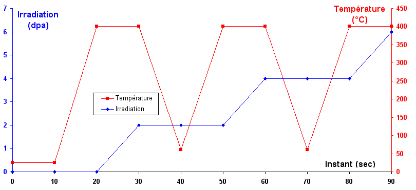
Figure 1.3-a : Temperature and irradiation conditions at all nodes as a function of time.
The modeling is done a first time with the swelling characteristics that correspond to the upper bound and then a second time with the swelling characteristics that correspond to the lower bound.