1. Reference problem#
1.1. Geometry#
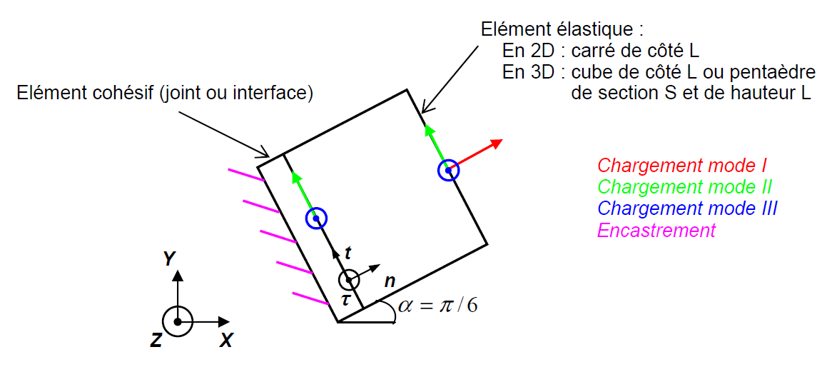
Figure 1: Representation of the system of two elements in plane \((X,Y)\). We choose \(L\mathrm{=}1\mathit{mm}\).
1.1.1. Geometry: case X- FEM#
In the models in formulation XFEM, there is no longer a cohesive joint or interface element in the model, but the cohesive law is defined on the interface using the DEFI_CONTACT command, as one would do for a contact law. Consequently, the square is meshed with a few elements and the line of discontinuity is introduced in the middle of the square, in an irregular manner: it intersects elements that are elastic in this case.
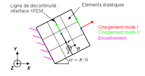
Figure 2: Modeling X- FEM in plane \((X,Y)\). We choose \(L=1\mathrm{mm}\).
1.2. Material properties#
1.2.1. Cohesive laws#
1.2.1.1. Material RUPT_FRAG#
**Cube:* elastic
Young’s module: \(E=0.5\mathrm{MPa}\) (except for J, K and L models where \(E=100\mathrm{MPa}\) is taken, this choice is purely practical)
Poisson’s Ratio \(\nu =0\)
Joint element: laws CZM_EXP_REG, CZM_LIN_REG
Interface element: laws CZM_OUV_MIX, CZM_EXP_MIX,,, CZM_TAC_MIX, CZM_FAT_MIX
Mixed law for linear finite elements: law CZM_LIN_MIX
Critical surface energy density: |
\({G}_{c}=0.9N/\mathrm{mm}\) |
(keyword: GC) |
critical stress: |
\({\sigma }_{c}=1.1\mathrm{MPa}\) |
(keyword: SIGM_C) |
Joint element: |
||
penalization of adherence |
PENA_ADHERENCE = \({10}^{-3}\mathrm{mm}\) |
(keyword: PENA_ADHERENCE) |
(small energy regulation parameter at 0, see []) |
||
criminalization of contact |
PENA_CONTACT = 1 (by default) |
(keyword: PENA_CONTACT) |
Interface element: |
||
Penalization of Lagrangian |
PENA_LAGR =100 (by default) |
(keyword: PENA_LAGR) |
Slip stiffness |
RIGI_GLIS =10 (by default) |
(keyword: RIGI_GLIS) |
Mixed law for linear finite elements: |
||
Penalization of Lagrangian |
PENA_LAGR =10 |
(keyword: PENA_LAGR) |
NB: Material data is of course not intended to represent a particular material. They are only intended for numerical validation tests.
1.2.1.2. Material RUPT_DUCT#
**Cube:* elastic
Young’s module: \(E={10}^{6}\mathrm{MPa}\) (this choice is purely practical)
Poisson’s Ratio \(\nu =0\)
Interface element: law CZM_TRA_MIX
Critical surface energy density: |
\({G}_{c}=0.9N/\mathrm{mm}\) |
(keyword: GC) |
critical constraint: |
\({\sigma }_{c}=9\mathrm{MPa}\) |
(keyword: SIGM_C) |
Extrinsic form coefficient |
\(0.0625\) |
(keyword: COEF_EXTR) |
Plastic tray form factor |
\(0.3125\) |
(key word: COEF_PLAS) |
Lagrangian penalty |
PENA_LAGR =100 (by default) |
(keyword: PENA_LAGR) |
Slip stiffness |
RIGI_GLIS =10 (by default) |
(keyword: RIGI_GLIS) |
NB: Material data is of course not intended to represent a particular material. They are only intended for numerical validation tests.
1.3. Boundary conditions and loads#
Embedment: The imposed displacements are zero on the face of the cohesive element opposite to the elastic element.
In mode \(I\): An imposed displacement
is applied to the face of the elastic element opposite the joint (see FIG. 1).
DX= 2.16506351 |
DY= 1.250 |
DZ= 0 |
In mode \(\mathrm{II}\): Imposed displacement
is applied to all the nodes of the solid element.
DX= -1.250 |
DY= 2.16506350946110 |
DZ= 0 |
In mode \(\mathrm{III}\): Imposed displacement
is applied to all the nodes of the solid element.
DX= 0.0 |
DY= 0.0 |
DZ= 2.5 |
For laws CZM_OUV_MIX, CZM_EXP_MIX and CZM_TAC_MIX, the same vectors normalized to 1 are used.
For fatigue law CZM_FAT_MIX (in \(I\) mode only) the same vectors normalized to \(\mathrm{0,094}\) are used. This value corresponds to the magnitude of the load because this one is multiplied by a cyclic function, zero at zero, which is equal to 1 at odd times and 0 at even times.
For the ductile law CZM_TRA_MIX (in \(I\) mode only) the same vectors normalized to 1 are used. Cyclic loading is applied to test all the states of the law but also monotonic loading. The tests are carried out with the first load.
1.3.1. Loading: case X- FEM#
Embed: The movements imposed are zero on the left side of the square.
In mode \(I\): An imposed displacement
is applied to the right side of the square (see figure 2).
DX= 2.16506351 |
DY= 1.250 |
DZ= 0 |