1. Reference problem#
1.1. Geometry#
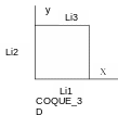
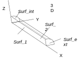
The geometry is chosen deliberately simple, to translate a state of homogeneous stresses and deformations, as is the case in uniaxial traction. In the case \(1D\) and \(\mathrm{3D}\), this is a bar with a diameter \(\varphi =6\mathit{mm}\) and a length of \(L=0.1m\). In \(\mathrm{3D}\), we only mesh a quarter of the bar. The traction is carried out at an imposed displacement in \(\mathrm{1D}\) and \(\mathrm{3D}\) with the length of the test piece. In case COQUE_3D, the side of the plate is square, and \(\pi \frac{{\varphi }^{2}}{4}\) thick (so that the forces are identical to case \(\mathrm{1D}\)).


For the case of flexure with thermal expansion, 4 bars are used instead of one, offset symmetrically in Y and Z of \({e}_{y}={e}_{z}=2.5\mathit{mm}\).
1.2. Material properties#
YOUNG module = \(2.E11\mathrm{Pa}\)
Poisson’s ratio \(\nu =0.3\)
Thermal expansion coefficient \(\alpha =1.2E-5\)
Keyword CORR_ACIER:
Damage coefficient D_ CORR = 0.2
Work hardening parameters ECRO_K = \(500\mathrm{MPa}\)
Elastic limit |
ECRO_M = \(2.781\) |
SY = \(500.\mathrm{MPa}\) |
1.2.1. Pure traction modeling#
The degree of corrosion is determined using the CREA_CHAM command:
NOM_CMP = “CORR” VALE = 0.0%, 2.5%, and 13%
1.2.2. Flexural modeling with thermal expansion#
The degree of corrosion is zero:
NOM_CMP = “CORR” VALE = 0.0% The imposed temperature field varies linearly from \({T}_{\mathit{ini}}=20°\) to \({T}_{\mathit{final}}=120°\).
1.3. Boundary conditions and loads#
1.3.1. 1D modeling#
Moves \(\mathit{DX}\) \(\mathit{DZ}\) and \(\mathit{DY}\) blocked at point \(A\)
Displacement \(\mathit{DX}\) and \(\mathit{DZ}\) imposed at point \(B\)
1.3.2. 3D modeling#
Displacement \(\mathit{DX}\) prevented on \({\mathit{Surf}}_{\text{int}}\)
Displacement \(\mathit{DY}\) prevented on \({\mathit{Surf}}_{1}\)
Displacement \(\mathit{DZ}\) prevented on \({\mathit{Surf}}_{2}\)
Displacement \(\mathit{DX}\) imposed on \({\mathit{Surf}}_{\mathit{ext}}\)
Modeling COQUE_3D:
Displacement \(\mathit{DX}\) prevented on \(\mathit{Li4}\)
Displacement \(\mathit{DY}\) prevented on \(\mathit{Li1}\)
Displacement \(\mathit{DX}\) imposed on \(\mathit{Li3}\)
1.3.3. Flexural modeling with thermal expansion#
Embedding at point \(A\),
According to \(Y\), a force \({F}_{y}\) is imposed at the point \(B\) in order to be placed at the elastic limit.
Knowing that at point \(A\) we have \({M}_{z}={F}_{y}L\) on the one hand, and \({M}_{z}=4{e}_{y}{\sigma }_{\mathit{xx}}\pi \frac{{\varphi }^{2}}{4}\) on the other hand, and that at the elastic limit \({\sigma }_{\mathit{xx}}=\mathit{SY}\) we then impose \({F}_{z}=4{e}_{y}\mathit{SY}\pi \frac{{\varphi }^{2}}{4}\frac{1}{L}\simeq 1413.7167N\).
1.4. Initial conditions#
Zero stresses and deformations.