1. Reference problem#
1.1. Geometry and loading#
A notched axisymmetric specimen of type \(\mathrm{AE4}\) is considered. The cohesive zone represented by interface elements (modeling A) or joint elements (modeling B) is positioned on line \(\mathrm{AB}\).
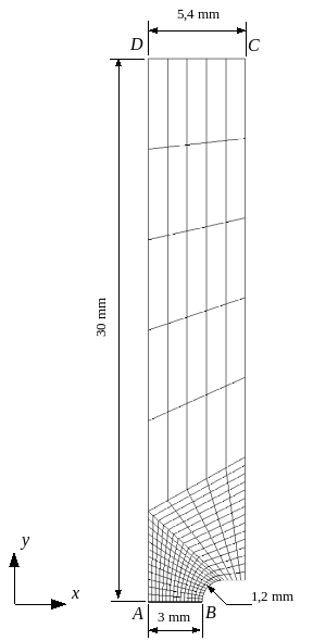
Figure 1: Geometry of specimen \(\mathrm{AE4}\).
1.2. Material properties#
To describe the behavior of the axisymmetric specimen material (bulk material), an elastoplastic behavior law with isotropic work hardening is used (law VMIS_ISOT_TRAC).
We take: \(E=207\mathit{GPa}\) and \(\nu =0.3\) and the work hardening curve used is given below:
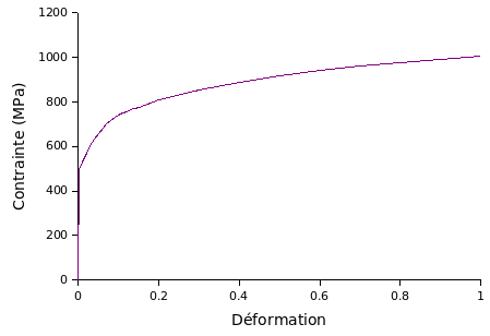
Figure 2: Isotropic work hardening curve of solid material.
The crack is represented with two different laws for models A and B:
Modeling A:
For interface elements the following parameters are used in law CZM_TRA_MIX:
\({\sigma }_{c}=1200\mathit{MPa}\), \({G}_{c}=130\mathit{MPa}\cdot \mathit{mm}\), \({\delta }_{e}=0.01\mathit{mm}\), \({\delta }_{p}=0.07\mathit{mm}\), \({\delta }_{c}=0.157\mathit{mm}\),
The resulting law is shown schematically below.
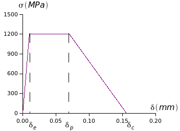
Figure 3: Law of behavior of interface elements.
NB: Only half of the crack is modelled thanks to the symmetry of the problem, the toughness of the material is \({\mathrm{2G}}_{c}\).
Modeling B:
For joint elements the following parameters are used in law CZM_LIN_REG:
\({\sigma }_{c}=1200\mathit{MPa}\), \({G}_{c}=130\mathit{MPa}\cdot \mathit{mm}\), \(\mathit{pena}\mathit{adherence}=1.E-5\)
NB: Only half of the crack is modelled thanks to the symmetry of the problem, the toughness of the material is \({\mathrm{2G}}_{c}\).
1.3. Boundary conditions and loading#
With reference to FIG. 1, the boundary conditions are as follows:
trip to \(X\) blocked on line \(\mathrm{AD}\),
imposed displacement \(l\) in the direction \(Y\) on line \(\mathrm{DC}\).
The evolution of displacement \(l\) over time is given in the following table:
Time \(\mathrm{[}s\mathrm{]}\) |
0 |
1 |
Displacement \(l\) \(\mathrm{[}\mathit{mm}\mathrm{]}\) |
0 |
0.5 |
The cohesive zone is represented by the interface elements on line \(\mathrm{AB}\). The upper lip of the interface elements is called \(\mathrm{AB}\) and the lower lip is called \(A\text{'}B\text{'}\). The boundary conditions on the interface elements are:
move to \(X\) imposed on the lips \(\mathrm{AB}\) and \(A\text{'}B\text{'}\): \({\mathrm{DX}}_{\mathrm{AB}}={\mathrm{DX}}_{A\text{'}B\text{'}}\)
trip to \(Y\) blocked on line \(A\text{'}B\text{'}\).