3. Modeling A#
3.1. Characteristics of modeling#
This is an axisymmetric \(\mathrm{2D}\) modeling, where we can identify 2 groups of elements:
Axisymmetric modeling (keyword AXIS) for concrete and steel elements.
Axisymmetric crack modeling (keyword AXIS_JOINT) for the joint element.
Concrete and steel are modelled with QUAD4 elements.
The interface is modelled with degenerate QUAD4 elements (nodes combined).
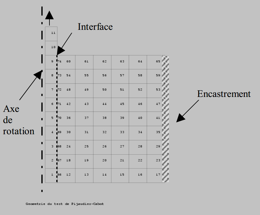
Figure 4.1-a: Axisymmetric test modelling
3.2. Characteristics of the mesh#
Number of knots: 94 (with 20 knots combined)
Number of meshes and type: 11 QUAD4 for steel
9 QUAD4 for the interface
54 QUAD4 for concrete.
3.3. Tested sizes and results#
We test the components \(\mathit{xy}\) of the element that correspond to the tangential components of the local law of behavior in the interface, using the constraint field SIEF_ELGA. The values are tested at the Gauss 2 point of the joint element, at 4 different time steps: at the beginning of loading, during the growth phase of the damage, in the peak of maximum strength and after the peak of bond strength.
Field SIEF_ELGA component SITX
Identification |
Reference |
\(\text{\%}\) tolerance |
For an imposed displacement \({U}_{\mathit{TT}}\mathrm{=}0.2\mathit{mm}\) |
-7.20 E+00 |
5 |
For an imposed displacement \({U}_{\mathit{TT}}\mathrm{=}0.8\mathit{mm}\) |
-1.14 E+01 |
5 |
For an imposed displacement \({U}_{\mathit{TT}}\mathrm{=}1.0\mathit{mm}\) |
-1.26 E+01 |
5 |
For an imposed displacement \({U}_{\mathit{TT}}\mathrm{=}1.6\mathit{mm}\) |
-1.22 E+01 |
5 |
3.4. Evolution of damage#
To observe the coherence of the evolution of the damage in the various connecting elements, the graph of the damage variable in relation to the imposed displacement is constructed.
