3. Modeling A#
3.1. Characteristics of modeling#
The bi-supported structure of length \(\mathrm{0,25}m\), extending between \(Z=-\mathrm{0,1}m\) and \(Z=\mathrm{0,15}m\), is connected at the levels of the nodes at positions \(\mathrm{0,0}m\) and \(\mathrm{0,05}m\) to a 3D model by the 3D_ POU option of the LIAISON_ELEM keyword from AFFE_CHAR_MECA.
It is modelled by Timoshenko beam elements (POU_D_T) and quadratic solid elements (PENTA15 and HEXA20).
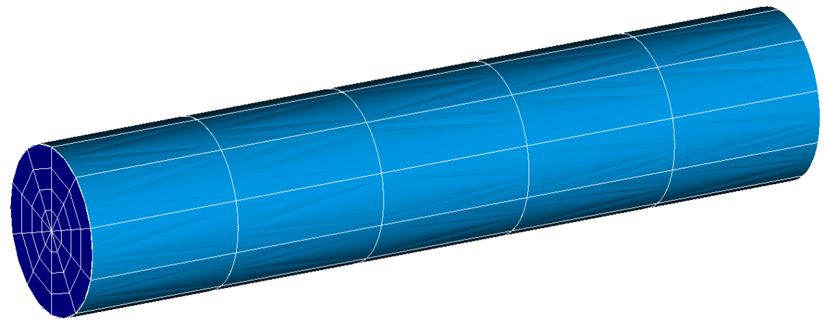
Image 3.1-1:3D solid model mesh
DYNA_LINE_TRAN calculates the dynamic response of the structure for 3 s, due to a nodal force of a value equal to 100 N on the 3D mesh node located at \(Z=\mathrm{0,02}m\). The switch from the 1D model to the 1D-3D mixed model is done at the moment \(\mathit{Tb}=2s\).
3.2. Characteristics of the mesh#
Number of stitches HEXA20 |
150 |
Number of stitches PENTA15 |
50 |
Number of stitches POU_D_T |
20 |
Table 3.2-1
3.3. Tested sizes and results#
The tables below give the numerical values tested in this test case. These are the minimum and maximum movements in X of a 3D mesh node located at \(Z=\mathrm{0,04}m\).
Identification |
Maximum Time |
Reference Type |
Reference Value |
Tolerance |
Minimal X displacement |
2.2115 s |
“AUTRE_ASTER” |
-0.0003266 |
|
Maximum X displacement |
2.7065 s |
“AUTRE_ASTER” |
+0.0003264 |
|
Table 3.3-1 : Summary of tested results