1. Reference problem#
1.1. Geometry#
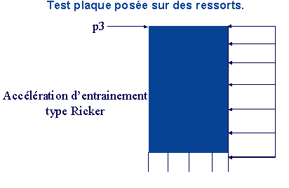
Figure 1.1-1: Plate on spring supports subjected to imposed acceleration
The plate has a width of \(4m\) (direction \(X\)), a height of \(8m\) (direction \(Y\)), and a thickness of \(1m\) in the \(Z\) direction normal to its plane.
A double series of springs is assigned to the lower edge of the plate. A first series of 5 springs to represent the support of the plate and a second series of 5 springs interposed between the first and the lower edge of the plate to represent the contact springs by penalization.
1.2. Material properties#
For the material of the plate, we have:
\(E\mathrm{=}1.4\mathrm{\times }{10}^{8}\mathit{Pa}\) |
|
|
Proportional damping (RAYLEIGH):
\(C=\alpha K+\beta M\) with \(\alpha =5.0\times {10}^{–3}s\) and \(\beta =0.1{s}^{–1}\).
The first set of springs to represent the support of the plate has stiffness characteristics of \(1.0\times {10}^{8}\mathrm{N.m}\) in the \(Y\) horizontal direction. The other stiffness characteristics in the other directions as well as those of the penalization contact springs are worth \(1.0\times {10}^{15}\mathrm{N.m}\).
1.3. Boundary conditions and loads#
On the whole structure we impose \(\mathrm{DZ}=\mathrm{DRY}=0\).
The embedment condition is imposed at the bottom of the first series of springs in order to represent the support of the plate: \(\mathrm{DX}=\mathrm{DY}=\mathrm{DZ}=0\).
Gravity is applied in the vertical direction \(Y\).
An imposed single-press acceleration in the horizontal direction \(X\) is also applied in the form of a Ricker signal with an amplitude \(0.23g\) (cf.).
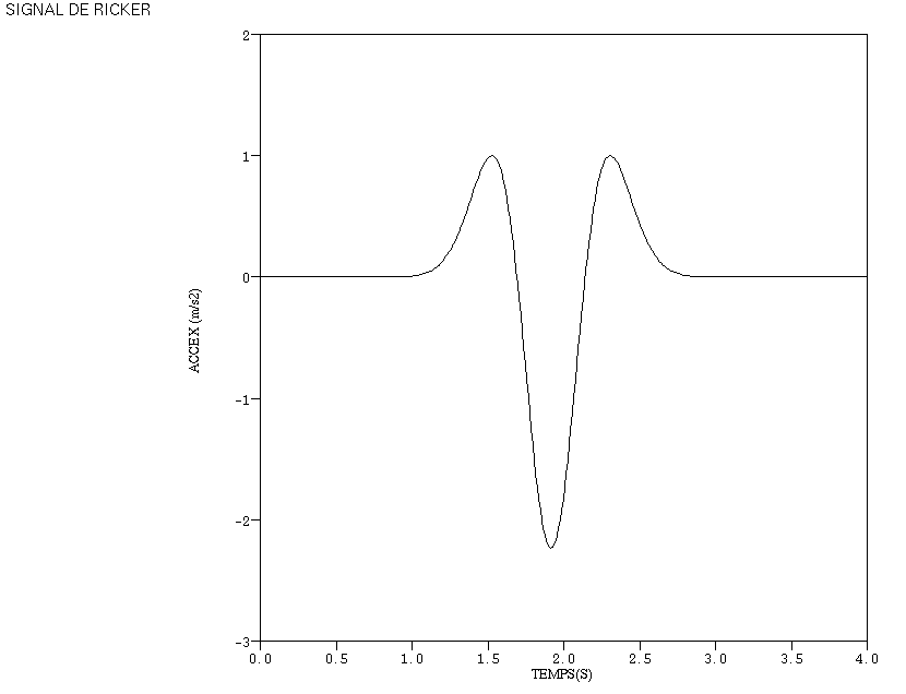
Figure 1.3-1: Imposed acceleration
1.4. Initial conditions#
The structure is initially at rest.