1. Reference problem#
1.1. Geometry#
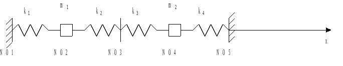
The system is composed of a set of 4 springs, 2 point masses, supported by 3 supports.
1.2. Material properties#
Link stiffness: \(k={k}_{\mathrm{1 }}={k}_{\mathrm{2 }}={10}^{\mathrm{3 }}N/m\) \({k}_{\mathrm{3 }}={k}_{\mathrm{4 }}=2k={2.10}^{\mathrm{3 }}N/m\);
point mass: \(m={m}_{\mathrm{1 }}={m}_{\mathrm{2 }}=\mathrm{10 }\mathrm{kg}\).
1.3. Boundary conditions and loads#
Boundary conditions:
The only authorized movements are translations according to axis \(x\).
Points \(\mathrm{NO1}\), \(\mathrm{NO3}\), and \(\mathrm{NO5}\) are embedded: \(\mathrm{dx}=\mathrm{dy}=\mathrm{dz}=\mathrm{drx}=\mathrm{dry}=\mathrm{drz}=0\).
The other points are free to translate in the direction \(x\): \(\mathrm{dy}=\mathrm{dz}=\mathrm{drx}=\mathrm{dry}=\mathrm{drz}=0\).
Loading:
The structure is subject to multiple spectral seismic excitation and to differential displacements:
The pseudo-acceleration oscillator response spectra are simplified. Only the values corresponding to the 2 natural frequencies of the system are mentioned. They do not depend on depreciation:
at node \(\mathit{NO}1\):
\({\mathit{SRO}}_{\mathit{NO}1}({f}_{1})={A}_{11}=7m/{s}^{2}\)
\({\mathit{SRO}}_{\mathit{NO}1}({f}_{2})={A}_{21}=5m/{s}^{2}\)
at node \(\mathit{NO}3\):
\({\mathit{SRO}}_{\mathit{NO}3}({f}_{1})={A}_{12}=7.7m/{s}^{2}\)
\({\mathit{SRO}}_{\mathit{NO}3}({f}_{2})={A}_{22}=5.5m/{s}^{2}\)
at node \(\mathit{NO}5\):
\({\mathit{SRO}}_{\mathit{NO}5}({f}_{1})={A}_{13}=12m/{s}^{2}\)
\({\mathit{SRO}}_{\mathit{NO}5}({f}_{2})={A}_{23}=6m/{s}^{2}\)
The excitations at nodes \(\mathit{NO}1\) and \(\mathit{NO}3\) are correlated. Two uncorrelated groups of supports are formed: group 1 is composed of nodes \(\mathit{NO}1\) and \(\mathit{NO}3\); group 2 consists of the only node \(\mathit{NO}5\). The same multiple spectral seismic excitation is identical for the two models A and B.
The differential movements are as follows:
Modeling A:
at node \(\mathit{NO}1\):
\({\mathit{DDS}}_{\mathit{NO}1}={D}_{1}=-0.04m\)
at node \(\mathit{NO}3\):
\({\mathit{DDS}}_{\mathit{NO}3}={D}_{2}=-0.044m\)
at node \(\mathit{NO}5\):
\({\mathit{DDS}}_{\mathit{NO}5}={D}_{3}=0.06m\)
Modeling B:
to support group 1 (DDS intra-group equals):
\({\mathit{DDS}}_{\mathit{NO}1}={\mathit{DDS}}_{\mathit{NO}3}={D}_{1}=-0.04m\)
to support group 2:
\({\mathit{DDS}}_{\mathit{NO}5}={D}_{2}=0.06m\)
1.4. Initial conditions#
The system is at rest.