1. Reference problem#
1.1. Geometry#
The concrete console is modelled by shell elements (DKT). The reinforcement layers (not eccentric) are modelled by models GRILLE_ENCENTRE for modeling A, MEMBRANE for modeling B and GRILLE_MEMBRANE for modeling C.
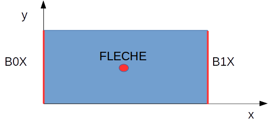
Figure 1-1: Definition of geometry
1.2. Material properties#
Concrete console: \(E=3.{10}^{10}\mathit{Pa}\), \(\nu =0\), \(\rho =2500\mathit{kg}/{m}^{3}\)
Thickness of the console: \(0.2m\); ANGL_REP = (0; 0)
Steel frame sheets: \(E=2.{10}^{11}\mathit{Pa}\), \(\nu =0\), \(\rho =7800\mathit{kg}/{m}^{3}\)
High reinforcement sheet: section per linear meter = \(0.2{m}^{2}/\mathrm{ml}\); ANGL_REP = (0; 0)
Low reinforcement sheet: cross section per linear meter = \(0.2{m}^{2}/\mathrm{ml}\); ANGL_REP = (0; 0)
1.3. Boundary conditions and loads#
Boundary conditions and loads break down as follows:
Recessed \(\mathrm{B0X}\) and \(\mathrm{B1X}\) edges
Nodal force \(\mathit{FX}={10}^{7}N\) at node \(\mathit{FLECHE}\) (node in the center of the plate), applied with the following multiplier function \(f\):
Time (s) |
\(f\) |
0 |
0 |
0.001 |
1 |
0.01 |
1 |