2. Modeling A#
This is” 3D “modeling, in thermal and mechanical terms.
2.1. Characteristics of the mesh#
The mesh contains all types of linear meshes that can support finite elements X- FEM in “3D” modeling. The cracks are arranged in such a way that all the X- FEM elements of the modeling are tested. The mesh, as well as the two cracks considered (a circular crack and an interface) are represented in the figure below.
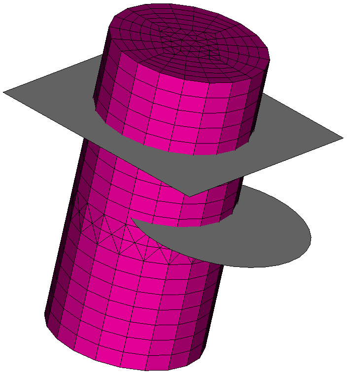
Figure 2.1-1: mesh A and crack locations
The characteristics of the mesh are summarized in the table below.
SEG2 |
|
|
|
|
|
|
||
80 |
228 |
540 |
540 |
1988 |
1988 |
918 |
1000 |
1700 |
The mesh also contains two orphan nodes, from which two POI1 meshes are constructed to assign two MECA_DIS_TR_N elements.