2. Modeling A: mesh crack#
In this modeling, the crack is meshed, and the standard finite element method is used.
to perform the calculation.
2.1. Characteristics of the mesh#
The structure is modelled by a cracked mesh composed of 13874 tetrahedra (see [Figure 2.1-a]).
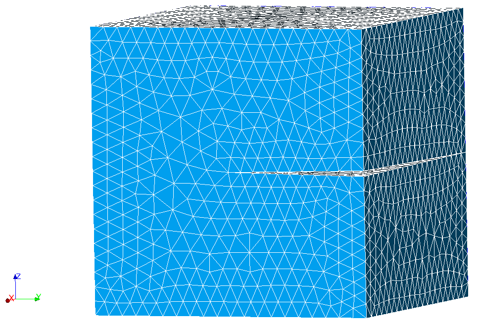
Figure 2.1-a: Cracked mesh
2.2. Tested sizes and results#
The values of \(K1\) are tested on the first three nodes of the crack bottom. Indeed, the orientation of the crack implies that \(K1\) cannot be calculated on certain nodes. We test the nodes concerned to verify that Code_Aster assigns them the value of the nearest neighbor node or the calculation of \(K1\) could be performed.
Identification |
Reference Type |
Reference Value |
Node 1 |
“NON_REGRESSION” |
212813.877395 |
Node 2 |
“NON_REGRESSION” |
212813.877395 |
Node 3 |
“NON_REGRESSION” |
212813.877395 |
We also test the values of \(\mathit{COOR}\text{\_}X\), \(\mathit{COOR}\text{\_}Y\), \(\mathit{COOR}\text{\_}Z\), \(\mathit{TEMP}\) and \(\mathit{NEUT}1\) at node 1 in order to verify that these components are indeed present in the output table for case FEM.