1. Reference problem#
1.1. Geometry#
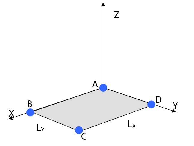
3D plate:
Length \(X\): \({L}_{X}\mathrm{=}2.0m\)
Length \(Y\): \({L}_{Y}=1.0m\)
Thickness: \(e=0.5m\)
Local coordinates of points \(A\), \(B\),, \(C\) and \(D\)
\({X}_{A}=0.0;{Y}_{A}=0.0;{Z}_{A}=0.0\)
\({X}_{B}=2.0;{Y}_{B}=0.0;{Z}_{B}=0.0\)
\({X}_{C}=2.0;{Y}_{C}=1.0;{Z}_{C}=0.0\)
\({X}_{D}=0.0;{Y}_{B}=1.0;{Z}_{B}=0.0\)
The orientation of the plate in the global coordinate system is obtained by two rotations:
\(\alpha \mathrm{=}30°\) around \(Z\)
\(\beta \mathrm{=}60°\) around the new \(X\text{'}\) axis
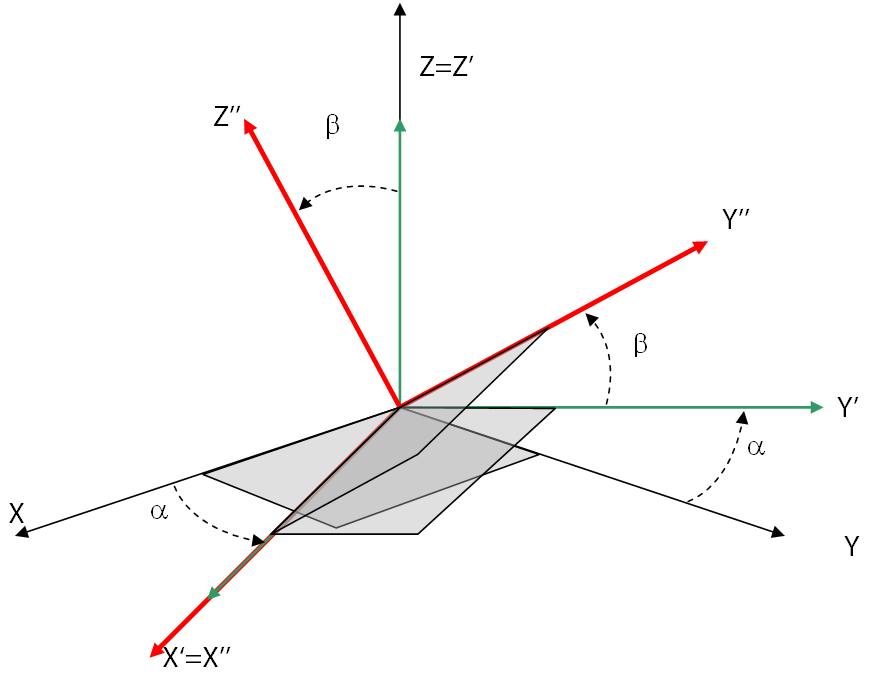
\(X;Y;Z\): global axes
\(X\text{'}\text{'};Y\text{'}\text{'};Z\text{'}\text{'}\): local axes in final position
1.2. Material properties#
Concrete:
Young’s module: \(E={3.7272}^{10}\mathrm{Pa}\)
Poisson’s ratio: \(\nu =0.0\)
1.3. Boundary conditions and loads#
On points \(A\) and \(B\) we block the movements along \(X,Y,Z\) and the rotations around the axes \(X,Y,Z\):
\({D}_{X}^{A}=0.0;{D}_{Y}^{A}=0.0;{D}_{Z}^{A}=0.0;{\mathrm{DR}}_{X}^{A}=0.0;{\mathrm{DR}}_{Y}^{A}=0.0;{\mathrm{DR}}_{Z}^{A}=0.0\)
\({D}_{X}^{B}=0.0;{D}_{Y}^{B}=0.0;{D}_{Z}^{B}=0.0;{\mathrm{DR}}_{X}^{B}=0.0;{\mathrm{DR}}_{Y}^{B}=0.0;{\mathrm{DR}}_{Z}^{B}=0.0\)
On points \(C\) and \(D\) we apply a loading according to \(Z\):
\({F}_{Z}=-100.0N\)