3. Modeling A#
3.1. Characteristics of modeling#
3D modeling is used. For an interface and for the only « catalog of predefined shapes » and « fields at nodes » methods in DEFI_FISS_XFEM, we use a D_ PLAN modeling of the same geometry limited to the \((X,Y)\) plane because these methods are not available in 3D.
3.2. Characteristics of the mesh#
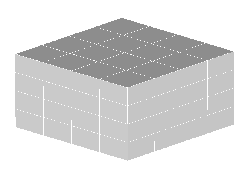
The 3D mesh contains 64 elements of type HEXA8 of dimension \(\mathrm{1x1x0.5}\mathrm{mm}\):
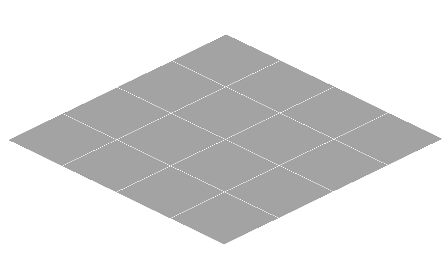
The D_ PLAN mesh contains 16 elements of type QUAD4 of dimension \(\mathrm{1x1}\mathrm{mm}\):
The same mesh is used for both the structure and the grid.
3.3. Tested sizes and results#
In each node, we test the difference between the level set on the mesh of the structure and the level set on the mesh of the grid. A value exactly equal to zero is obtained everywhere, which makes it possible to check the coincidence of fields at the nodes between structure and grid.
3.4. notes#
In the test we are forced to use a tolerance in TEST_TABLE. This tolerance is taken to be equal to 0.01. This has no influence on the test results because you are testing values that are always exactly equal to zero.