1. Presentation of the test case#
1.1. Geometry#
The geometry, created under CIVIL_MASTER, is on 3 levels. It is composed of 6 sails, 3 floors, 4 columns and an opening located in a veil. It is illustrated by the following figure:
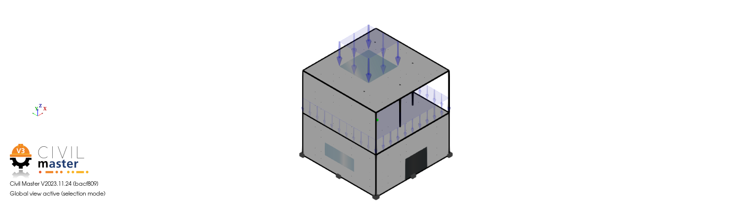
Figure 1.1-1: Geometry
1.2. Meshing#
The mesh is as follows:
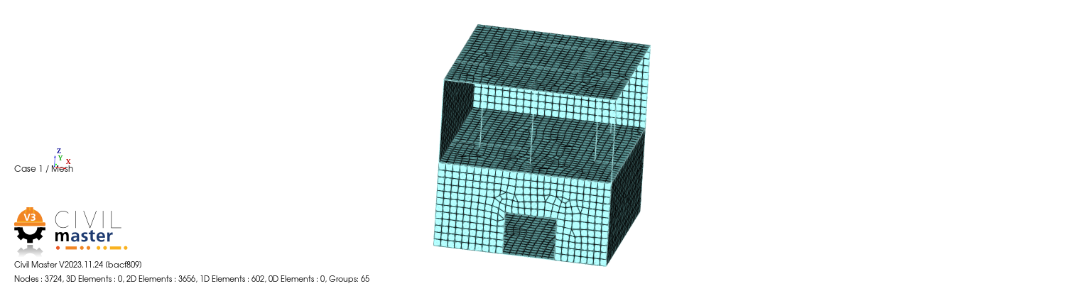
Figure 1.2-1: Meshing
1.3. Material & Geometric Properties#
Concrete material is applied to the entire structure.
The Young \(E=30000\mathit{MPa}\) module
Poisson’s ratio \(\mathrm{\nu }=\mathrm{0,2}\)
The thicknesses of the walls and floors are \(200\mathit{mm}\) and the beams have a square section with a \(200\mathit{mm}\) side.
1.4. Loading#
The load is:
The base is recessed.
The weight is applied to the entire structure,
Surface pressure \(F=-10\mathit{kN}/m\mathrm{²}\) is applied to the roof of the structure and to a lower web (Fig 1).
Two load cases are defined and correspond respectively to Weight (Case G) and Pressure (Case Q). Then, POST_COMBINAISON is used to sum the loads.
1.5. Validation#
The displacement in a node of the intermediate floor is extracted following the calculations of the load cases and then of POST_COMBINAISON by ensuring that the sum of the displacements of the load cases (Case G: \(\mathit{DZ}=-\mathrm{0,0107}m\), Case Q \(\mathit{DZ}=-\mathrm{0,0153}m\)) corresponds to the displacement resulting from POST_COMBINAISON \(\mathit{DZ}=-\mathrm{0,026}m\).
This documentation is deliberately brief.