3. Operands#
3.1. Operand MAILLAGE#
♦ MAILLAGE = my
Name of the mesh on which we will define the crack base and the lips.
3.2. Crack bottom description#
The crack bottom is defined by the set of ordered nodes in the crack bottom. If the keyword GROUP_NO_ORIG is not defined, the order in which these nodes are declared, using segment cells, will define the direction of travel of the curvilinear abscissa of the crack bottom. It is thus left to the user to compose an ordered list, in the sense of the connectivity of the mesh, by increasing curvilinear abscissa.
It is also possible to provide a list of mesh segments without worrying about the order. The data of an origin node, provided that it corresponds to one end of the path defined by the mesh segments, then makes it possible to order the list of nodes.
Moreover, in 3D, for a current node at the crack bottom, the direction of propagation is defined as being the average of the normal to the mesh segments of the crack bottom to its left and to its right. For end nodes, the normal is calculated from a single mesh, and may therefore be less accurate.
The code therefore provides for a correction of this normal by taking into account the edges of the structure.
3.2.1. Keyword factor FOND_FISS#
3.2.1.1. Keyword TYPE_FOND#
There are two ways to define the crack bottom:
If the crack bottom is defined by an open curve (as opposed to the bottom defined by a closed curve), enter TYPE_FOND =” OUVERT “. This value is the by default.
If the crack bottom is defined by a closed curve, enter TYPE_FOND =” FERME “.
3.2.1.2. Keyword GROUP_NO#
/♦ GROUP_NO = grno
This keyword can only be used in 2D.
A group containing a single node corresponding to the bottom of the crack is expected.
This keyword can only be used in 2D.
3.2.1.3. Keyword GROUP_MA#
/♦ GROUP_MA = grma
This keyword can only be used in 3D.
Group of SEG2 or SEG3 cells, ordered or not ordered in relation to the crack bottom.
3.2.1.4. Keyword GROUP_NO_ORIG#
/GROUP_NO_ORIG = grno
A single node, or group of nodes, containing a single node. To be one end of the path defining the crack bottom, it must belong to one and only one GRMA mesh. This keyword can only be set if GROUP_MA is set. This keyword can only be used in 3D.
3.2.1.5. Keyword GROUP_NO_EXTR#
/GROUP_NO_EXTR = grno
A node group that contains a single node. This data is optional and is only used to verify that the end node obtained by the operator is the one the user is thinking of. The code will stop in error if it’s not the case. This keyword can only be set if GROUP_NO_ORIG is set. This keyword can only be used in 3D.
3.2.1.6. Keyword GROUP_MA_ORIG#
/GROUP_ MA _ ORIG = gr ma
A mesh group containing a single mesh. This data, mandatory in the case of a closed 3D front, allows, together with the keyword GROUP_NO_ORIG, to define a direction of travel of the crack front by increasing curvilinear abscissa. This meaning ranges from the node defined by GROUP_NO_ORIG to the second end node of the mesh defined by GROUP_MA_ORIG.
3.3. Description of lips#
Two initial configurations are treated:
if the lips are stuck
if the lips are peeled off
In the case of glued lips, two cases are distinguished:
if the mesh is complete then the algorithm requires the definition of the upper and lower lips.
if the mesh is to be completed by symmetry with respect to the mean plane of the lips then the algorithm requires the sole definition of the upper lip.
The crack propagation direction and the normal to the crack plane are calculated for each node at the crack bottom.
In the case of detached lips, it is necessary to give the normal to the plane of the crack using the NORMALE operand (2D and 3D for flat cracks only).
For later use in POST_K1_K2_K3 (keyword FOND_FISS), the lips must be glued.
For non-planar 3D cracks, the direction of propagation of the crack at any point in the crack bottom is constructed in this operator and is used by the operator CALC_G [U4.82.03].
Currently, fracture mechanics calculations by CALC_G, POST_K1_K2_K3 or other methods are not possible for 3D defects that are not flat and whose lips are detached.
3.3.1. Keyword CONFIG_INIT#
The initial configuration is that described by the mesh. The lips are:
glued if the angle between the 2 lips is less than or equal to 5°;
peeled off otherwise.
Note: The calculation of stress intensity factors with the operator POST_K1_K2_K3 [U4.82.05] , * or with l “ option “K” of the operator CALC_G [U4.82.03] , can only be done if CONFIG_INIT =” COLLEE “.
3.3.2. Keyword SYME#
This keyword makes it possible to specify whether the modeling used takes into account a symmetry of the structure with respect to the mean planes of the crack lips (see Figure 3.1). If SYME = “OUI”, the value of the energy restoration rate G (s) and those of the stress intensity factors corresponding to the symmetry mode will automatically be multiplied by 2 and that of G_Irwin by 4 (see [U4.82.03] for CALC_G and [U4.82.05] for POST_K1_K2_K3).
If SYME = “OUI” and CONFIG_INIT =” COLLEE “, the definition of the upper lip of the crack (LEVRE_SUP, §3.3.3) makes it possible to know which side of the bottom the crack is located on.
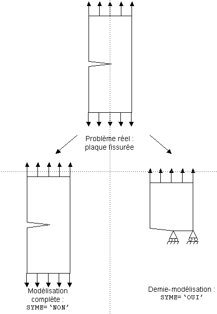
Figure 3.1: Definition of symmetry.
3.3.3. Keyword LEVRE_SUP#
◊ LEVRE_SUP =
Defines all the faces of the elements that rest on the upper lip of the crack. All of these faces are specified by the operand:
The meshes are therefore surface if the model is 3D and linear if the model is 2D.
3.3.4. Keyword LEVRE_INF#
◊ LEVRE_INF =
Defines all the faces of the elements that rest on the lower lip of the crack. If the crack is on a plane of symmetry, this keyword should not be entered.
All of these faces are specified by the operand:
3.3.5. Operand NORMALE#
This operator should only be defined in the case of a crack with detached lips (CONFIG_INIT =” DECOLLEE “). This concerns cases of open defect or notch.
The key word NORMALE is used to specify the vector normal to the plane of these lips, and therefore to the crack itself. This vector is used at any point on the crack bottom to determine the direction of propagation and therefore assumes that the crack is flat. The normal is then not the normal to the lips, but to the plane of propagation (plane of symmetry).
/♦ NORMALE = (Nx, Ny, Nz)
The keyword NORMALE makes it possible to introduce the components Nx, Ny, Nz into the global coordinate system of a normal \(\text{N}\) at the crack plane with the following convention of meaning:
In 3D, \(\text{n}={\text{Γ}}_{\text{0}}\wedge \text{N}\), where \(\text{n}\) is the external normal to the crack in the plane of the lips, \({\text{Γ}}_{\text{0}}\) is the oriented crack background (defined by the key word FOND_FISS),
in 2D, normal \(\text{N}\) is defined such that the \(({\text{N}}_{\text{0},}\text{t},\text{N})\) coordinate system is direct, with:
\({\text{N}}_{\text{0}}\) the node at the bottom of the crack,
\(\text{t}\) the direction of propagation of the crack.

In all cases, \(\text{N}\) is automatically standardized. It is necessary to give the three components of the vector even in 2D.
3.4. Operand PREC_NORM#
This operand is only useful in the 3D case, before a calculation with POST_K1_K2_K3 [U4.82.05].
Parameter PREC_NORM defines the precision used in the search for lip nodes that are in directions normal to the bottom of the crack: for the interpolation of movement jumps, we in fact use nodes whose distance d to the normal line at the bottom and passing through a node at this bottom verifies:
\(\text{d}<\text{PREC\_NORM}\text{.}{\text{l}}_{\text{f}}\)
where \({\text{l}}_{\text{f}}\) is the minimum distance between two successive nodes at the crack bottom. Increasing the value of PREC_NORM is equivalent to increasing the number of nodes potentially selected for the calculation of \(\text{K}\) in POST_K1_K2_K3.