2. Operands#
2.1. Operand MODELE#
♦ MODELE = model
Concept produced by the operator AFFE_MODELE [U4.41.01] to define the types of finite elements assigned to mesh cells.
2.2. Operand CHAM_MATER#
♦ CHAM_MATER = chmat
Concept produced by the operator AFFE_MATERIAU [U4.43.02] allowing materials to be assigned to the meshes of the mesh.
2.3. Operand CARA_ELEM#
♦ CARA_ELEM = Caelem
Concept produced by the operator AFFE_CARA_ELEM [U4.42.01] allowing mechanical and geometric characteristics to be assigned to the elements of the studied structure.
2.4. Operand GROUP_MA_BETON#
♦ GROUP_MA_BETON = grmabe
Name of the mesh group (or groups) of meshes representing the concrete structure. The geometric location of projection of the cables is thus precisely defined, a preliminary step in determining the kinematic relationships between the degrees of freedom of the cable nodes and the degrees of freedom of the nodes of the concrete structure.
Notes:
1- It is possible to provide here a list of groups of elements, especially in the case where all the concrete meshes surrounding the cable do not have the same behavior. However, it is essential that all the concrete meshes concerned have the same characteristics BPEL_BETON .
2- Meshes modeling concrete can only be 3D meshes or 2D meshes in the case of plate modeling ( DKT, Q4GG).
2.5. Definition of cable#
2.5.1. Keyword DEFI_CABLE [DEFAUT]#
DEFI_CABLE
Keyword factor allowing the definition of a cable by designating the topological entities of the mesh that represent it. Multiple occurrences are allowed, in order to be able to define several cables. The cables can be defined individually or by providing a table (see test SSNV229a)
/♦ GROUP_MA = Grmaca
Name of the group of elements in the mesh representing the cable.
♦ GROUP_NO_ANCRAGE = l_gnoa
List of node groups that define anchors. The cardinal on this list must be less than or equal to 2. In each node group, only the first node in the group will be used as anchor.
/♦ TABL_CABLE = table
When the number of cables is important, it may be easier to have defined them using a table containing 3 columns, defining the group of elements of the cable and the name of the 2 groups of nodes defining the anchors. Columns should be named GROUP_MA, GROUP_NO1, GROUP_NO2.
This table can be defined outside Code_Aster (Excel, Python) and read with the LIRE_TABLE command.
Example:
# LISTE CABLE
GROUP_MA GROUP_NO1 GROUP_NO2
CAB1 CAB1_I CAB1_F
CAB3 CAB3_I CAB3_F
2.5.2. Keyword MODI_CABLE_ETCC#
◊ MODI_CABLE_ETCC
Keyword factor allowing the definition of a cable by designating the topological entities of the mesh that represent it and providing for each of the cables the initial short-term tension in order to make it possible to calculate the losses by relaxation of the steel according to ETCC (adherent cable only). Multiple occurrences are allowed, in order to be able to define several cables. To use it, you must have specified TYPE_RELAX =” ETCC_REPRISE “.
♦ GROUP_MA = Grmaca
Name of the group of elements in the mesh representing the cable.
♦ GROUP_NO_ANCRAGE = l_gnoa
List of node groups that define anchors. The cardinal on this list must be less than or equal to 2. In each node group, only the first node in the group will be used as anchor.
♦ TENSION = table
Table containing the tension in the cable for all curvilinear abscissa (table with 2 twin-post car hoists). This table is used to calculate steel relaxation losses in cases where the user has opted for option TYPE_RELAX = “ETCC_REPRISE”. This table is obtained using a POST_RELEVE_T on the nodes of the cable under study, after a first static calculation.
2.5.3. Keyword MODI_CABLE_RUPT#
◊ MODI_CABLE_RUPT
Keyword factor allowing the definition of a cable by designating the topological entities of the mesh that represent it. This keyword makes it possible to bypass the voltage calculation by retrieving the table provided under the keyword TENSION. The technique makes it possible to simulate the breakage of a cable with re-anchoring (adherent cable only).
Multiple occurrences are allowed, in order to be able to define several cables.
♦ GROUP_MA = Grmaca
Name of the group of elements in the mesh representing the cable.
♦ GROUP_NO_ANCRAGE = l_gnoa
List of node groups that define anchors. The cardinal on this list must be less than or equal to 2. In each node group, only the first node in the group will be used as anchor.
♦ TENSION = table
Table containing the voltage in the cable for all curvilinear abscissa (table with 2 twin-post car hoists) and which will become the reference voltage. This table is obtained via a POST_RELEVE_T on the nodes of the cable studied after a first calculation and then modified as the user wishes.
2.6. Operand ADHERENT#
♦ ADHERENT =/'OUI' [DEFAUT]
/”NON”
This keyword allows you to indicate whether you want to model cables adhering to concrete (ADHERENT = “OUI”) or sliding or rubbing cables (ADHERENT = “NON”). For non-adherent cases, modeling CABLE_GAINE and the law of behavior CABLE_GAINE_FROT should be used to represent steels. The adherent case can be simulated with modeling BARREou CABLE_GAINE.
Note:
In the case ADHERENT = “NON”, the voltage profile is calculated even if it is not used afterwards (neither in AFFE_CHAR_MECA/RELA_CINE_BP, nor in CALC_PRECONT).
2.7. Operand TYPE_ANCRAGE#
♦ TYPE_ANCRAGE = l_tya
List of text-type arguments characterizing cable anchors: “ACTIF” or “PASSIF” (only legal arguments). This list must contain 2 arguments, no more and no less, and must be ordered according to the list of nodes defining the anchors (operand GROUP_NO_ANCRAGE above). Note that if multiple cables are defined in DEFI_CABLE then the first argument of TYPE_ANCRAGE applies to all of the first nodes that define the anchors. Idem for the second argument.
Notes:
1- The operator reconstructs the related path leading from the first to the second anchor of the cable by going through the meshes that represent it. The non-existence of a connected path between the two anchors causes the program to stop in a fatal error.
2- Active anchors are those where an initial tension is applied.
2.8. Operand TENSION_INIT#
♦ TENSION_INIT = f0
Value of the initial force applied to active cable anchorages.
This value should be positive.
2.9. Operand RECUL_ANCRAGE#
♦ RECUL_ANCRAGE = delta
Value of recoil at active cable anchorages.
This value should be positive.
2.10. Choice of the type of calculation to take into account the relaxation of steels#
◊ TYPE_RELAX = /” SANS “, [DEFAUT]
/” ETCC_DIRECT “, /” ETCC_REPRISE “,
Keyword to define whether or not tension losses due to relaxation of steel are taken into account by the regulatory method, and if so which one (ETCC or BPEL). Since this keyword factor is optional, by default, tension losses due to relaxation of steel are not taken into account.
2.10.1. TYPE_RELAX =” SANS “#
This is the default value. In this case, this type of loss is not taken into account by a regulatory method. On the other hand, it can be taken into account using the law of viscoelastic behavior RELAX_ACIER for the cable (cf. [R5.03.09]).
2.10.2. TYPE_RELAX =” BPEL “#
In this case, the BPEL formula is applied, and the R_J keyword must be entered (see § 2.11 for details).
2.10.3. TYPE_RELAX =” ETCC_DIRECT “#
In this case, the ETCC formula is applied, but the force used only takes into account losses due to friction and anchor recoil (see § 4).
It is necessary to fill in the keyword NBH_RELAX (see § 2.12).
2.10.4. TYPE_RELAX =” ETCC_REPRISE “#
In this case, the exact formula for ETCC is applied. This involves doing an initial calculation without relaxation and recovering the tension in the cable. Then it is necessary to define the cable according to MODI_CABLE_ETCC instead of DEFI_CABLE.
It is necessary to fill in the keyword NBH_RELAX (see § 2.12).
2.11. R_J operand#
◊ R_J = \(\mathit{rj}\)
Parameter to be filled in only if TYPE_RELAX =” BPEL “.
Value of the dimensionless function \(r(j)\) characterizing the evolution of the relaxation of steel over time and only of steel (this coefficient does not apply to losses due to creep or shrinkage of concrete entered in BPEL_BETON in DEFI_MATERIAU); for example, BPEL 91 recommends:
\(r(j)=\frac{j}{j+9\times {r}_{m}}\) with \(j\) in days
and \({r}_{m}=\frac{\text{aire de la section de béton}}{\text{périmètre de la section de béton}}\equiv \text{rayon moyen}\)
This value must be positive or zero.
\(j\) corresponds to the date (in days) for which we want to estimate the stress state in the structure. In the case where, in structural design, the members are modelled with creep behavior, you should not enter this keyword in DEFI_CABLE_BP.
2.12. Operand NBH_RELAX#
◊ NBH_RELAX = \(\mathit{nh}\)
Parameter to be filled in only if TYPE_RELAX =” ETCC_DIRECT “or” ETCC_REPRISE “.
Time taken into account for the relaxation losses of steel in ETCC, expressed in number of hours.
The formula applied is as follows:
\(\mathrm{\Delta }{F}_{\mathit{pr}}=\mathrm{0,66}\text{.}{\mathrm{\rho }}_{1000}\text{.}{e}^{\mathrm{9,1}\frac{\stackrel{~}{F}(s)}{{P}_{\mathit{pk}}}}\text{.}{\left(\frac{\mathit{nh}}{1000}\right)}^{\mathrm{0,75}(1-\stackrel{~}{F}(s)/{P}_{\mathit{pk}})}\text{.}{10}^{-5}\stackrel{~}{F}(s)\)
where:
\({\rho }_{1000}\) is the value of the relaxation coefficient of steel at 1000 hours in%, entered under ETCC_ACIER.
\({P}_{\mathit{pk}}\) is the maximum tensile strength of steel at break, calculated from the data for F_ PRG under ETCC_ACIER.
\(\stackrel{̃}{F}\) is equal to the tension calculated according to ETCC taking into account the friction and anchor recoil losses if TYPE_RELAX =” ETCC_DIRECT “or the tension supplied by the user under MODI_CABLE_ETCC/TENSION in the other case.
2.13. Keyword CONE#
♦ CONE
This keyword factor makes it possible to define a geometric volume around the anchors, and to assign, at the output of AFFE_CHAR_MECA keyword RELA_CINE_BP, to all the nodes (concrete and cable) contained in this volume, a kinematic relationship of type LIAISON_SOLIDE (rigid body). The definition of this volume makes it possible to mitigate the stresses caused by the tensions generated by the tensions at the ends of the cables on the concrete. In reality, this phenomenon is avoided by setting up a stress diffusion cone (material harder than concrete) which distributes the prestress force over a large area of the concrete. In practice, since the cone is practically straight, a cylindrical volume is defined.
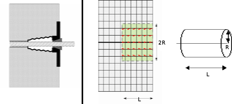
Real Situation |
Finite Element Modeling |
Figure 1: use of a diffusion cone: real situation and modeling
Note that several cones and therefore several rigid blocks are defined if the keyword PRESENT contains two “OUI” (one block per end of the cable) or if several cables are defined under DEFI_CABLE.
Note:
In practice, the cylinder is defined by the command DEFI_GROUP option TUNNEL. The methodology for extracting the nodes contained in the cone is described in document [U4.22.01] (command DEFI_GROUP).
♦ RAYON = radius
Cone radius.
♦ LONGUEUR = length
Length of the cone, in the curvilinear abscissa direction on the cable. The cone is defined as a succession of cylinders by stopping when the total length of the cylinders is equal to the length parameter.
♦ PRESENT = l_pre
This list must contain 2 arguments, no more and no less, and must be ordered according to the list of nodes defining the anchors (operand GROUP_NO_ANCRAGE above).
The only valid arguments are “OUI” or “NON”; they allow you to define the cone on both anchors (PRESENT =( “OUI”, “OUI”,)), on the first anchor (PRESENT =( “OUI”, “”, “NON”,)) or on the second anchor (PRESENT =( “NON”, “ OUI “,)). Note that if several cables are defined in DEFI_CABLE then the first argument of PRESENT applies to all the first nodes that define the anchors. Same for the second argument.
2.14. Operand TITRE#
◊ TITRE = l_title
List of text-type arguments defining a title attached to the [cabl_precont] concept.