3. Operands#
3.1. Operand INFO#
◊ INFO
If the value of INFO is 2, the operator prints in the file “MESSAGE”, for each occurrence of the keywords SECTION or FIBRE, the characteristics of each fiber (position and area).
Note:
All characteristics are given in relation to the axis defined in the operand COOR_AXE_POUTRE, by calling the coordinates of the section \(x\) (horizontal) and \(y\) (vertical) .
3.2. Tags SECTION and FIBRE#
♦ | SECTION
|FIBER
Define the relevant beam mesh entities and the sections that are assigned to them.
The keyword SECTION makes it possible to assign a section defined by a plane mesh (the elements of this mesh are the fiber sections). The fiber count is totally dependent on the mesh and the type of mesh (quadrangle or triangle).
The FIBRE keyword makes it possible to assign a section where the fibers are defined by « points ». The fibers are numbered from 1 to n in the order in which they were defined.
In the presence of the two keywords, the numbering of the fibers will start with the fibers defined under the keyword SECTION then with those defined under the keyword FIBRE. To get it, you can define INFO =2 in DEFI_GEOM_FIBRE.
Note:
Currently the number of fiber groups on a beam element is limited to 10.
3.2.1. Operands common to SECTION and FIBRE#
♦ GROUP_FIBRE
This operand allows you to define a name for the fiber group (24 characters). This name will be used in the DEFI_COMPOR operator to assign material and behavior to this group of fibers. Remember that all the fibers defined by an occurrence of SECTION or FIBRE will have the same behavior.
◊ COOR_AXE_POUTRE =( xg, yg)
This operand allows you to define the coordinates of the axis of the beam in the coordinate system of the straight section. Integrations (static moments or moments of inertia) will be made with respect to this axis. The position by default is \((\mathrm{0.0,}0.0)\).
◊ ANGLE =angle
This operand allows you to define the angle of rotation of the mesh definition coordinate system to make it correspond to the main coordinate system of the beam. this rotation is always performed after COOR_AXE_POUTRE. The angle by default is \(0.0\).
When the coordinates of the fibers are given either by a mesh (keyword SECTION) or by triplets of values (keyword FIBRE), they are in a coordinate system that is not linked to the beam. This makes it possible to define complex sections without having to define them in the main inertia coordinate system of the beam.
It is easier to configure the mesh of an angle section (figure) in coordinate \(({x}_{\mathrm{1,}}{y}_{1})\) than in coordinate system \(({x}_{\mathrm{2,}}{y}_{2})\). The mesh for the section is in plane \(\mathit{XY}\).
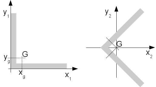
Figure 3.2.1-a: Corner section.
The characteristics of the beams (section, inertia,…) are defined in the main inertia frame of reference, it is therefore necessary to establish the relationship between the frame of definition of the fibers and the main frame of inertia of the beam. The keyword COOR_AXE_POUTRE defines the translation of the coordinate system linked to the mesh of the section to make it correspond to that of the beam. The keyword ANGLE allows you to rotate the mesh of the section to make it correspond to that of the beam.
In the example of the angle (figure), to make the mesh correspond to the main coordinate system of the beam section, you must fill in the two keywords:
COOR_AXE_POUTRE = (xg, yg)
ANGLE = -90
3.2.2. Operands specific to SECTION#
The fiber group is defined by a set of « surface » fibers.
♦ MAILLAGE_SECT
Name of the plane « mesh » that contains the « description of the section ».
The term « mesh » means a set of triangular cells with 3 knots and/or quadrilateral cells with 4 nodes. By « description of the section », we mean a part of this « mesh » specified by one of the TOUT_SECT or GROUP_MA_SECT operands. Each mesh represents the section of a fiber.
♦/TOUT_SECT
/GROUP_MA_SECT
Operands |
Content/Significance |
TOUT_SECT |
The section is defined by all the cells in the mesh defined under MAILLAGE_SECT |
GROUP_MA_SECT |
The section is defined by a list of mesh groups |
Notes:
Since it does not serve as a support for finite elements, the « mesh » does not have to have connectivity, it can be composed of a set of juxtaposed meshes or not.
The coordinates \(x\) and \(y\) of the plane mesh of the section ( \(x\) horizontal, \(y\) vertical) are defined in a plane perpendicular to the axis of the beam. To define the spin angle, that is to say the angle between the axis \(x\) of the plane mesh of the section and the axis \(Y\) of the beam element, you must use the keyword ORIENTATIONde the operator AFFE_CARA_ELEM.
3.2.3. Operands specific to FIBRE#
The fiber group is defined by a set of « point » fibers.
◊ CARA = “SURFACE” | “DIAMETER”
Allows you to specify whether the third value given for each fiber is the area or the diameter (see VALE).
♦ VALE
Each fiber is described by a triplet of values: \((x,y,\mathit{val})\) It is necessary to give the values according to this sequence, as many triplets as there are fibers.
\(x\) and \(y\) are the coordinates of the center of the fiber in a plane perpendicular to the axis of the beam.
\(\mathrm{val}\) is either the area of a fiber or the diameter of a cylindrical fiber.
The position of the coordinate system can be changed using COOR_AXE_POUTRE. To give a spin angle, use the ORIENTATION keyword from the AFFE_CARA_ELEM operator.
3.3. Keyword ASSEMBLAGE_FIBRE#
This key word makes it possible to define a fiber group assembly. The kinematics connecting the different fiber groups is particular and is used to account for phenomena specific to the modeling of fuel assemblies, cf. [R3.08.08] Multifiber beam element (right).
♦ GROUP_ASSE_FIBRE
This operand allows you to define a name for the fiber assembly group (24 characters). This name will be used in the DEFI_COMPOR operator to assign material and behavior to this fiber assembly group. Remember that all the fibers defined by an occurrence of GROUP_ASSE_FIBRE will have the same behavior.
♦ GROUP_FIBRE
This operand makes it possible to define the list of names of the fiber groups that will constitute the fiber assembly. Group names are defined either by SECTION/GROUP_FIBRE or by FIBRE/GROUP_FIBRE.
♦ COOR_GROUP_FIBRE
This operand makes it possible to define the coordinates of the center of gravity of the fiber groups defined under the keyword GROUP_FIBRE. It is a list of reals (x1, y1,…, xn, yn) that has 2 times the length of the list given under GROUP_FIBRE. The coordinates of the fiber groups are translated from (xi, yi).
♦ GX_GROUP_FIBRE
This operand makes it possible to define the torsion coefficient of the fiber groups defined under the keyword GROUP_FIBRE. It is a list of real (gx1,…, gxn) that has the same length as the list given under GROUP_FIBRE.