3. Operands#
3.1. Operand MAILLAGE#
♦ MAILLAGE = my,
[mesh] type mesh on which the modifications and/or verifications will be carried out.
Note:
It is possible to apply a and 3D modification*on a* initially two-dimensional mesh. *
3.2. Operand INFO#
◊ INFO =
Indicates the level of printing of operator results,
1 = |
no impression, |
2 = |
impression of meshes whose connectivity has been changed, including the printing of old and new connectivities. |
The prints are done in the file “MESSAGE”.
3.3. Keyword ORIE_FISSURE#
◊ ORIE_FISSURE =
This keyword is used to reorient (if necessary) the cells of a group forming a « monolayer » of elements. It works in 2D or 3D, with a linear or quadratic mesh [Figure 3.4-a].
Figure 3.4-a
Currently, this keyword is used to reorient joint elements and interface elements (models AXIS_xxx, PLAN_xxx, and 3D_xxx with xxx= JOINT or INTERFACE).
The user specifies (with the keyword GROUP_MA) what are the candidate meshes for reorientation (the « monolayer »).
These meshes must be « prisms » (QUAD in 2D, HEXA and PENTA in 3D).
The « transverse » direction to the layer is determined topologically (and not according to a flattening criterion). To be able to be reoriented, the elements of the layer must rely (via the bases of the prisms) on other meshes of the same dimension (2D or 3D) that do not belong to the group of cells to be reoriented.
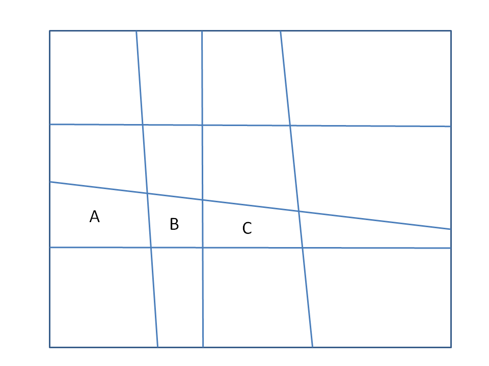
Consider the mesh (2D) opposite.
We want to reorient the group of the 3 cells A, B and C.
For cells A and B, the support cells (above and below) determine an unambiguous transverse orientation (vertical).
On the other hand, cell C has 3 support cells (top, bottom, right) and we do not know how to determine the transverse direction.
The reorientation algorithm is going to fail.
Note:
The « reorientation » we are talking about here actually consists in changing the definition of mesh connectivity. For example, in 2D, the convention is that sides 2 and 4 of the quadrangles are transverse to the layer.
List of mesh groups whose orientation you want to check (and possibly modify).
3.4. Keyword DEFORMEE#
♦ DEFORME/OPTION =” TRAN “
Option to add to the initial geometry of the ma mesh:
the values of TRANslation (dx, dy (+ dz in 3D)) of the displacement field depl given by the DEPL keyword;
Or a random quantity.
/DEPL = deep,
Displacement field used to update geometry
/ALEA = epsi,
A random quantity (delta) is added to each coordinate of each node of the mesh.
This quantity is obtained by the formula: delta=epsi*dim*alea ()
Where:
epsi is a number provided by the user (1.e-8 for example)
dim is the dimension of the mesh in the direction concerned by the component (X, Y, or Z)
alea () is a function that returns a pseudo-random number in the range
[-1,1].
Note:
*The possibility of randomly modifying the coordinates of a mesh is, in principle,**a « developer » feature. It is dangerous in certain situations: very flattened meshes (joints, … ) *
3.5. Keyword ORIE_PEAU#
◊ ORIE_PEAU =
This keyword is used to reorient edge cells so that their normals are consistent (outside the material). This keyword is valid for a two-dimensional (2D) or three-dimensional (3D) study. This is an essential prerequisite if, for example, one wants to apply a loading of pressure to this « skin ».
♦ GROUP_MA_PEAU = lgrma, [l_gr_ma]
Clusters of meshes to be reoriented.
The meshes are oriented in such a way that the normal is outgoing. For each edge mesh (edge or face), we look for the « volume » mesh that it « borders ». It is oriented in such a way that its normal is in the opposite direction to the vector connecting its first node to the barycenter of the volume cell.
It sometimes happens that the « skin » that you want to orient is inserted into the material (for example, when doing a calculation for which, cells are gradually added or removed from the model: modeling an excavation, or a construction by layers). The orientation algorithm described above then fails because there are generally 2 volume meshes on either side of the skin mesh. It is then not clear which one to use to orient the skin mesh.
To do this, we introduced the optional keyword GROUP_MA_INTERNE. This keyword allows the user to specify which « internal » meshes are to be used to orient the skin elements.
Example:
Let’s say 1 group of skin cells (GPEAU) that we want to orient with a normal directed towards the outside. It should be indicated that it is the skin of the group of « volume » elements GV2.
We will write:
ORIE_PEAU =_F (GROUP_MA_PEAU =” GPEAU “, GROUP_MA_INTERNE =” GV2”),
3.6. Keyword ORIE_NORM_COQUE#
◊ ORIE_NORM_COQUE = _F (
This keyword is used to check that in a list of surface meshes (shells), the normals are consistent with each other. Otherwise, some meshes are reoriented.
♦ GROUP_MA = lgrma, [l_gr_ma]
Surface mesh groups to be reoriented. The cells in lgrma must form a « connected » group so that they can be reoriented by continuity.
You can impose a sense of direction using the keywords GROUP_NO/VECT_NORM. If we do not do it, the orientation chosen will be that of the 1st stitch of LGRMA, but it is not necessarily the 1st stitch of the 1st GROUP_MA! It is therefore advisable to always use the VECT_NORM keyword.
◊ VECT_NORM = (n1, n2, [n3]), [L_r]
ni: 2 or 3 components (depending on the dimension) of the normal vector. It is also necessary to specify the support node for this normal:
◊ GROUP_NO = grno, [gr_no]
grno should be a GROUP_NO containing only one node.
The normal chosen will be the one that makes an acute angle with the vector given by VECT_NORM.
Note: if GROUP_NO is not given by the user, the code will automatically choose one of the nodes in GROUP_MA. It is therefore necessary to be careful in defining the latter, so that the normal is well defined across all the cells. In particular, cases should be avoided where the group does not define an almost flat topological area.
3.7. Keyword ORIE_LIGNE#
◊ ORIE_LIGNE = _F (
This keyword is used to check that in a list of line cells (beams), the tangents are consistent with each other. Otherwise, some meshes are reoriented.
♦ GROUP_MA = lgrma, [l_gr_ma]
Line cell groups to be reoriented. The cells in lgrma must form a « connected » group so that they can be reoriented by continuity.
You can impose a sense of direction using the keywords GROUP_NO/VECT_TANG. If we do not do it, the orientation chosen will be that of the 1st stitch of LGRMA, but it is not necessarily the first stitch of the first GROUP_MA! It is therefore advisable to always use the VECT_TANG keyword.
◊ VECT_TANG = (n1, n2, [n3]), [L_r]
ni: 2 or 3 components (depending on the dimension) of the tangent vector. It is also necessary to specify the support node for this normal:
◊ GROUP_NO = grno, [gr_no]
grno should be a GROUP_NO containing only one node.
The tangent chosen will be the one that makes an acute angle with the vector given by VECT_TANG.
3.8. Keyword MODI_MAILLE#
♦ OPTION = “NOEUD_QUART”,
Activates the movement of the middle nodes of the edges touching the crack bottom to a quarter of these edges (towards the crack bottom).
♦/GROUP_MA_FOND = lgma_fo, [l_gr_ma]
/GROUP_NO_FOND = lgno_fo, [l_gr_no]
In 2D, we enter the node at the bottom of the crack (by GROUP_NO_FOND).
In 3D, you enter either the nodes at the bottom of the crack, or the SEG3 mesh at the bottom of the crack (and not the mesh of the lips of the crack or the meshes of material attached to the bottom).
3.9. Keyword TRANSLATION#
Attention
This feature can be combined with ROTATION, but these operations are not commutative. Translation is always performed before rotation.
This feature cannot be combined with SYMETRIE.
◊ TRANSLATION = (n1, n2, [:ref:`n3 <n3>`]), [L_r]
Simple keyword for translating a mesh according to a vector.
3.10. Keyword ROTATION#
Attention
This feature can be combined with TRANSLATION, but these operations are not commutative. On the other hand, it is not allowed to use ROTATION, , MODI_BASE, and SYMETRIEen at the same time. Translation is always performed before rotation.
◊ ROTATION =
Keyword factor for the rotation of any axis of a mesh.
♦ POIN_1 = (ni, n2, [n3]), [L_r]
Coordinates of the first point to define the axis of rotation.
♦/POIN_2 = (ni, n2, [n3]), [L_r]
/DIR = (ni, n2, [n3]), [l_R]
Coordinates of the second point or direction to completely define the axis of rotation.
♦ ANGLE = a, [R]
Angle of rotation expressed in degrees.
The rotation takes place in the anticlockwise direction, in relation to its oriented axis. This axis passes through the point POIN_1 and its orientation is given, either by the vector DIR, or by the original vector POIN_1 and the end vector POIN_2.
Rotation is defined by:
Let \(\text{M}(x,y,z)\) be a point in space, we impose on it a rotation of angle \(\alpha\) (in radians) whose axis passes through \(\text{P}(\mathit{px},\mathit{py},\mathit{pz})\) and has the direction \(\text{D}(\mathit{dx},\mathit{dy},\mathit{dz})\). So \(\text{M}\) becomes \(\text{M}’\) after the rotation:
\(\text{M'}\mathrm{=}\text{P}+\mathrm{cos}\alpha \mathrm{.}\text{PM}+(1\mathrm{-}\mathrm{cos}\alpha )\mathrm{.}(\text{PM}\mathrm{.}\text{D})\mathrm{.}\text{D}+\mathrm{sin}\alpha (\text{D}\mathrm{\wedge }\text{PM})\)
3.11. Keyword ECHELLE#
Attention
This feature can be used with TRANSLATIONet ROTATION. Scaling, when requested, is always done after TRANSLATIONet ROTATION.
This feature cannot be combined with SYMETRIE.
◊ ECHELLE = n 1, [R]
Simple keyword for scaling a mesh according to a real one.
Let \(\text{M}(x,y,z)\) be a point in the mesh,
it will become, through this transformation of relationship \(\mathit{n1}\): \(\text{M}’(\mathit{n1}\mathrm{\cdot }x,\mathit{n1}\mathrm{\cdot }y,\mathit{n1}\mathrm{\cdot }z)\).
3.12. Keyword MODI_BASE#
Attention
This feature is not allowed with ROTATIONet * SYMETRIE.
◊ MODI_BASE =
Keyword factor for the change of base in which the coordinates of a mesh are expressed. The change of reference always takes place between 2 orthonormal bases.
♦ VECT_X = (n1, n2, [n3]), [L_r]
Coordinates of the first vector of the new base, of any norm.
◊ VECT_Y = (n1, n2, [n3]), [L_r]
Coordinates of the second vector of the new base (not used in 2D), also of any standard.
In 2D, all you have to do is give the VECT_X axis, and Code_Aster automatically builds the second vector to define a direct orthogonal base. A test verifies whether VECT_X has a non-zero norm.
In 3D, we check that VECT_X and VECT_Y have a non-zero norm and we check that they are orthogonal. The third vector that completes the base is constructed as being the vector product of VECT_X with VECT_Y. This ensures the construction of a direct orthogonal base.
Then, in all cases (2D and 3D), the vectors in the base are normalized to 1, so the user does not have to worry about it. So we finally have a direct orthonormal base.
In 3D, we therefore expect the data from VECT_X and VECT_Y **, the first two vectors of the new base. Then the base change is defined as:
3.13. Keyword SYMETRIE#
Attention
This feature cannot be combined with TRANSLATION, , ROTATION, * ECHELLEet MODI_BASE.
♦ POINT = (n1, n2, [:ref:`n3 <n3>`]) [L_r]
Coordinates of a point belonging to the line in 2D or to the plane in 3D.
♦ AXE_1 = (n1, n2, [:ref:`n3 <n3>`]) [L_r]
Directional vector of the line in 2D or 1st vector used to describe the plane.
◊ AXE_2 = (n1, n2, n3) [l_R]
2nd vector used to describe the plane.
In 2D, the symmetry is in relation to a line, which is in plane \(\mathit{OXY}\). To define this line we must give the direction vector of the line (AXE_1) and a point (POINT) belonging to this line.
In 3D, the symmetry is in relation to a plane. To define this plane, we must give 2 vectors of the plane (AXE_1, AXE_2) and a point (POINT) belonging to this plane.
In all cases (2D or 3D), symmetry is achieved with respect to a plane. In 2D, the second vector needed to define the plane is set to AXE_2 = (0.0, 0.0, -1.0).
The algebraic distance \(\delta\) between a point \(\text{M}(x,y,z)\) and a plane passing through the point \(\text{Mo}(\mathit{xo},\mathit{yo},\mathit{zo})\) with the perpendicular vector \(\text{V}\mathrm{=}\text{AXE\_1}\mathrm{\wedge }\text{AXE\_2}\mathrm{=}(a,b,c)\) is:
\(\delta \mathrm{=}\frac{a(x\mathrm{-}{x}_{0})+b(y\mathrm{-}{y}_{0})+c(z\mathrm{-}{z}_{0})}{\sqrt{{a}^{2}+{b}^{2}+{c}^{2}}}\)
The coordinates of the point \(\text{M}\text{'}\) symmetric of the point \(\text{M}\) with respect to the plane are given by:
\(\mathit{OM}\text{'}\mathrm{=}\mathrm{-}2\delta \mathrm{.}\frac{V}{\mathrm{\parallel }V\mathrm{\parallel }}+\mathit{OM}\)
3.14. Keyword ABSC_CURV#
◊ ABSC_CURV = _F ( ... ),
Calculate the curvilinear abscissa for all SEG cells provided using the keywords GROUP_MA or TOUT =” OUI “.
For each of the nodes of the cells concerned, its curvilinear abscissa is calculated taking into account its possible curvature.
The GROUP_NO_ORIG keyword allows the user to choose the origin of curvilinear abscissa (the node where the abscissa is zero). The origin must be one of the ends of the line on which we want to calculate the curvilinear abscissa.
This option is necessary, for example, to perform a modal calculation for a tube with external and internal fluid, when the density of the external fluid is defined as a function of the curvilinear abscissa.
Notes:
All the meshes concerned must be of the SEG2, SEG3 or SEG4 type.
SEG2 cells are considered straight and SEG3 and SEG4 stitches are assumed to be in the shape of a circular arc.