4. Operands#
4.1. Operand MAILLAGE#
♦ MAILLAGE = my_1
ma_1 is the name of the initial mesh that you want to reproduce before « enriching » it with new meshes or knots, or « impoverishing » it.
Note:
The keyword MAILLAGEest mandatory except for the use of the keywords ECLA_PG and GEOM_FIBRE.
4.2. Keyword CREA_MAILLE#
◊ CREA_MAILLE
An occurrence of this keyword factor makes it possible to define a new group of elements made up of new cells, which themselves rely on existing nodes.
To duplicate several groups of cells, repeat the keyword factor CREA_MAILLE.
Unlike the command DEFI_GROUP [U4.22.01] for which the mesh concept always maintains the same number of meshes and nodes, here the number of meshes of the new mesh is increased (the number of nodes remains the same because the new meshes are based on existing nodes).
This can facilitate the creation of new geometric locations in order to be able to apply different models to the same group of elements.
4.2.1. Operand NOM#
♦ NOM = name
One gives here the name of the new group of elements that will be created.
4.2.2. Operands GROUP_MA/TOUT#
♦ | GROUP_MA = lgma,

| ALL = 'YES',
All the meshes provided by the user with these two keywords will be duplicated and the new meshes will be combined into a group of elements with the name specified by the keyword NOM. If all the cells to be duplicated contain duplicate cells, they are eliminated.
4.2.3. Operands PREF_MAILLE/PREF_NUME#
◊ PREF_MAILLE = pre_ma
The value of this keyword is used to define the prefix for the new cells. The name of the new mesh is obtained by replacing the first character of the name of the mesh to be duplicated by the text specified under the keyword PREF_MAILLE. In the case where this new name has a length of more than eight characters, we end up in a fatal error with an error message. This should normally never happen if the prefix provided is a single character long. This keyword is optional: the prefix by default is then « E »
◊ PREF_NUME =/ind
If an integer ind is given under the keyword PREF_NUME, the number of the new cells is constructed by concatenating the uppercase text given under the keyword PREF_MAILLE and an integer obtained by incrementing ind by 1 each time new cells are created.
**Note: the user must be careful in choosing their prefix to avoid new meshes having the same name as old meshes. This name collision is detected by the command and leads to Code_Aster stopping.*
4.3. Keyword CREA_POI1#
◊ CREA_POI1
An occurrence of this factor keyword makes it possible to define “POI1” meshes (single-node mesh) based on knots or mesh knots.
4.3.1. Operands TOUT/GROUP_MA/GROUP_NO#
♦ | ALL = 'YES',

| GROUP_MA = lgma,

| GROUP_NO = no,
All the nodes that belong to entities specified by the user with these five keywords generate a POI1 mesh. The mesh created will have the same name as the node that supports it.
4.3.2. Operand NOM_GROUP_MA#
♦ NOM_GROUP_MA = name_ma
All POI1 meshes created in this way can be grouped into the same group of elements named name_ma.
4.3.3. How do I create several POI1 stitches on each knot?#
The POI1 meshes created by the CREA_POI1 keyword have the same names as the nodes from which they were created. It is therefore not possible to create several POI1 meshes on the same node using several occurrences of the CREA_POI1 keyword.
A possible workaround is to combine the use of CREA_MAILLAGE/CREA_POI1 with CREA_MAILLAGE/CREA_MAILLE. For example, to create 2 POI1 stitches on each node in the “GNO1” group, you could do:
MA2 = CREA_MAILLAGE (MAILLAGE = MA1,
CREA_POI1 = _F (NOM_GROUP_MA =” GM1 “, GROUP_NO =” GNO1”))
MA3 = CREA_MAILLAGE (MAILLAGE = MA2,
CREA_MAILLE =_F (NOM_GROUP_MA =” GM2 “, GROUP_MA =” GM1”, PREF_MAIL =”S”))
4.4. Keyword MODI_MAILLE#
◊ MODI_MAILLE
An occurrence of this keyword factor makes it possible to transform a set of meshes.
4.4.1. Operand OPTION#
♦ OPTION =/'SEG3_4'
/”TRIA6_7” /”QUAD8_9” /”QUAD_TRIA3”
This keyword indicates the transformation to be performed:
transformation of segments with three nodes into segments with four nodes (usable for example for modeling “TUYAU” [U3.11.06],
transformation of triangles with six knots into triangles with seven knots,
transformation of eight-node quadrangles into nine-node quadrangles,
transformation of quadrangles into triangles with 3 nodes:
transformation of QUAD4 meshes into two TRIA3 meshes
transformation of QUAD8 meshes into six TRIA3 meshes
transformation of QUAD9 meshes into eight TRIA3 meshes
4.4.2. Operands PREF_NOEUD/PREF_MAILLE/PREF_NUME#
◊ PREF_NOEUD =/pre_nd,
/”NS”,
The value of this keyword defines the prefix for the new nodes. The name of the new node is obtained by adding the text specified under the PREF_NOEUD keyword in front of its old name. In the case where this new name has a length of more than eight characters, we end up in a fatal error with an error message.
◊ PREF_MAILLE = pre_ma
See CREA_MAILLE.
◊ PREF_NUME =/ind,
/1,
If an integer ind is given under the keyword PREF_NUME, the number of the new nodes (new cells) is constructed by concatenating the uppercase text given under the keyword PREF_NOEUD (PREF_MAILLE) and an integer obtained by incrementing ind by 1 each time new nodes (new cells) are created.
Notes:
The user must be careful in choosing his prefix to avoid that the new knots (new stitches) have the same name as old knots (new stitches). This name collision is detected by the command and leads to Code_Aster stopping.
An automatic procedure for cutting quadrangle cells into triangles can generate a kind of « polarization » of the mesh: starting with a mesh QUADdonné, all the diagonals are oriented in the same direction.
Warning: using the “QUAD_TRIA3” option may lead to a non-compliant mesh. See [§ 3].
4.5. Keyword LINE_QUAD#
◊ LINE_QUAD
This feature allows you to create a quadratic mesh from a linear mesh.
It can only be applied to a part of the mesh (keyword GROUP_MA), but it is not recommended. See [§ 3].
The mesh groups are maintained, as are the node groups (without change).
As with the refinement of a mesh, the nodes created are not introduced into the existing node groups.
If a group of nodes corresponds to an edge, after LINE_QUAD, this group does not contain the middle nodes of edges. To get a complete GROUP_NO, you can use for example the command DEFI_GROUP/OPTION = “APPUI”.
4.5.1. Operands GROUP_MA/TOUT#
♦ | GROUP_MA = lgma,

| ALL = 'YES',
The set of cells specified by the user with these two keywords will be transformed into square cells.
Attention, the use of the GROUP_MA keyword is not recommended. See [§ 3].
4.5.2. Operands PREF_NOEUD/PREF_NUME#
As for MODI_MAILLE.
4.6. Keyword PENTA15_18#
This factor keyword works like the factor keyword LINE_QUAD (same syntax). It is used to transform PENTA15 into PENTA18 by adding nodes to the midpoints of quadrangular faces.
Attention, the use of this keyword is not recommended if the mesh contains other types of solid meshes (HEXA and PYRAM). See [§ 3].
4.7. Keyword HEXA20_27#
This factor keyword works like the factor keyword PENTA15_18 with hexahedra. It is used to transform HEXA20 into HEXA27 by adding nodes to the midpoints of the faces and the center of each hexahedron.
Attention, the use of this keyword is not recommended if the mesh contains other types of solid meshes (PENTA and PYRAM). See [§ 3].
4.8. Keyword MODI_HHO#
This option allows you to create a mesh compatible with HHO elements from any mesh. This option is essential for using the HHO method on tetrahedra, prisms, and pyramids. The mesh created is composed of SEG3, QUAD9, TRIA7,,,, HEXA27,, TETRA15, PENTA21, and PYRAM19.
Attention, the use of this keyword is not recommended if it is applied only to a part of the mesh because it can generate non-compliant meshes. See [§ 3].
4.9. Keyword COQUE_SOLIDE#
This option allows you to create a mesh compatible with elements COQUE_SOLIDE from a mesh of elements HEXA8 or PENTA6. This option is essential to use the COQUE_SOLIDE modeling, the new meshes HEXA9 and PENTA7 contain a node in the middle of the support that allows you to take into account the degree of freedom of pinching. The mesh created is therefore composed of SEG2, QUAD4,, HEXA9, PENTA7 and TRIA3.
In the case of hexahedral elements, it is necessary to enter the keyword GROUP_MA_SURFqui identifying the surface to orient the cells. This surface can be the top one or the bottom one. This is not necessary for prisms since in this configuration, it is the fact that TRIA3qui identifies the upper and lower surfaces of the shell.
Since this option creates new nodes, the keywords PREF_NOEU and PREF_NUME can be used (see § 4.4.2).
4.10. Keyword RAFFINEMENT#
This option allows you to create a uniformly refined mesh from a given mesh. The option applies to the entire mesh to avoid any compliance issues. The principle of uniform refinement is to cut each edge in half and then to propagate the cut to the other meshes. It is equivalent to the adaptation “RAFFINEMENT_UNIFORME” of the MACR_ADAP_MAIL macro. Attention, the size of the mesh increases very quickly and the quality of this one may decrease if the initial mesh is not of good enough quality. It is advisable to start with a mesh that already represents the geometry well, especially if it is curved, before refining.
◊ TOUT = “OUI”, [DEFAUT]
Refinement applies to the entire mesh.
◊ NIVEAU =/ind, [I]
/1, [DEFAUT] The keyword NIVEAU makes it possible to specify the number of successive refinements desired.
4.11. Keyword QUAD_LINE#
◊ QUAD_LINE
This feature allows you to create a linear mesh from a quadratic mesh, it can only be applied to a part of the mesh (pay attention in this case to the connection of the linear and quadratic areas). See [§ 3].
4.11.1. Operands GROUP_MA/TOUT#
♦ | GROUP_MA = lgma,
| ALL = 'YES',
The cells specified by the user with these two keywords will be transformed into square cells.
Attention, the use of the GROUP_MA keyword is not recommended. See [§ 3].
4.12. Keyword REPERE#
◊ REPERE
An occurrence of this factor keyword makes it possible to define a new mesh based on the old mesh by changing the coordinate system.
This feature is used in particular in the macro command MACR_CARA_POUTRE [U4.42.02] for calculating the warping constant.
4.12.1. Operands TABLE/NOM_ORIG/NOM_ROTA/GROUP_MA#
♦ TABLE = tab
One gives here the name of the « geometric characteristics » concept table which contains, in particular, the coordinates of the center of inertia and of the center of torsion, the nautical angles defining the main inertia coordinate system,… This table can be obtained by the POST_ELEM command with the keywords factors CARA_GEOM or CARA_POUTRE [U4.81.22].
◊ NOM_ORIG =/'CDG',
/”TORSION”,
The center of the new coordinate system is indicated: the center of gravity or the center of torsion.
◊ NOM_ROTA =/'INERTIE',


The direction of the new coordinate system is indicated. Only one solution is possible: the directions are those of the main inertia coordinate system.


◊ GROUP_MA = GMA


If NOM_ORIG = 'CDG', you can specify the name of the group of elements whose center of gravity will be the origin of the new coordinate system. If GROUP_MA is not used, the center of gravity of the whole MODELE will be the origin of the new coordinate system.

If NOM_ORIG = 'TORSION', the key word GROUP_MA does not work.
4.13. Keyword COQU_VOLU#
◊ COQU_VOLU
From the data of a group of surface elements (QUAD, TRIA3), the volume mesh (,) is constructed by extrusion according to the normal of the elements (in a node, we take the average of the normals of the concurrent elements). HEXA8 PENTA6 A single element layer is created.
The operation only applies to linear meshes; if you want to create a quadratic mesh, simply use CREA_MAILLAGE/LINE_QUAD afterwards.
4.13.1. Operands NOM#
♦ NOM = name,
Name of the group of elements made up of the volume cells created during this operation.
4.13.2. Operands GROUP_MA#
♦ GROUP_MA = lgma,
Groups of meshes constituting the surface mesh to be extruded.
4.13.3. Operands EPAIS#
♦ EPAIS = ep,
Thickness of the element layer created (shell thickness).
4.13.4. Operands PLAN#
♦ PLAN = /' SUP ',
/” INF “, /” MOY “,
We specify here that the surface made of lgma will be the SUPérieur, INFérieur or MOYen plane of the shell.
4.13.5. Operands TRANSLATION#
♦ TRANSLATION = /' SUP ',
/” INF “,
In the case where PLAN =” MOY “, it is specified whether the initial surface consisting of lgma is translated into skin SUPérieure or INFérieure.
4.13.6. Operands PREF_MAILLE/PREF_NOEUD/PREF_NUME#
Same as CREA_MAILLE, except for the default value which is “V”.
4.14. Keyword CREA_FISS#
♦ NOM = nogma, [TXM] ♦ GROUP_NO_1 = gno1, [group_no] ♦ GROUP_NO_2 = gno2, [group_no] ♦ PREF_MAILLE = pre_ma, [Kn] ◊ PREF_NUME =/ind, [I] /1, [DEFAUT] ),
Allows you to create a crack with joint elements [R3.06.09] or elements with discontinuity [R7.02.12] along a line defined by two groups of nodes arranged opposite each other. The two groups of nodes must have the same number of nodes and be ordered beforehand (for example with DEFI_GROUP/CREA_GROUP_NO/OPTION =”NOE UD_ORDO “) so that their numbering « starts » on the same side (see).
We can then assign « joint » modeling to these new QUAD4 cells (for example “PLAN_JOINT”).
The meshes created will have a name formed from the prefix pre_ma followed by a number.
For example, if PREF_MAILE =”FS” and PREF_NUME =7, the stitches created will be called: FS7, FS8,…
We will also create a new GROUP_MA (called nogma) containing all the QUAD4 meshes created.
4.14.1. Operand NOM#
Name of the group of elements made up of the volume cells created during this operation.
4.14.2. Operands GROUP_NO_1/GROUP_NO_2#
Node groups that make up the lips of the crack. Node group GROUP_NO_1 carries local nodes 1 and 2 (the first node in the group has a local number equal to 1), GROUP_NO_2 carries local nodes 3 and 4 (the first node in the group has a local number equal to 4).
These groups of nodes must be chosen according to the geometry so that the local numbering of the elements is carried out in the trigonometric direction.
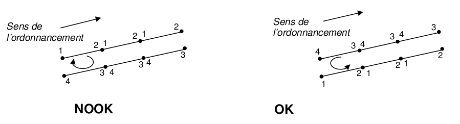
Figure 1: Segment Scheduling
4.14.3. Operands PREF_MAILLE/PREF_NUME#
As for MODI_MAILLE.
4.15. Keyword ECLA_PG#
◊ ECLA_PG
This factor keyword does not have to be used directly. It is used by the MACR_ECLA_PG [U4.44.14] command.
4.16. Keyword GEOM_FIBRE#
◊ GEOM_FIBRE
This keyword makes it possible to obtain the mesh created by defi_geom_fibre [U4.26.01]. This mesh contains all the fiber groups in the study as well as the mesh containing all the fibers.
4.17. Keyword RESTREINT#
This factor keyword (non-repeatable) makes it possible to generate a « sub » mesh extracted from an existing mesh.
The extracted (or « restricted ») mesh ma_2 is formed from a list of meshes provided by the user.
4.17.1. Maillages#
The keyword GROUP_MA allows you to define the meshes of the restricted mesh.
4.17.2. Knots#
The knots retained are those of the stitches retained. Additionally, if the GROUP_NO =lgno keyword is used, the nodes of the lgno groups are added.
4.17.3. Mesh groups#
The ma_2 mesh will contain all the LGMA GROUP_MA. In addition, if the keyword TOUT_GROUP_MA =” OUI “is used, the non-empty mesh groups of ma_1 are added.
4.17.4. Node groups#
The ma_2 mesh will contain all the GROUP_NO of lgno. Additionally, if the keyword TOUT_GROUP_NO =” OUI “is used, the non-empty ma_1 node groups are added.
4.18. Keyword DECOUPE_LAC#
♦ DECOUPE_LAC
This keyword makes it possible to obtain a mesh containing « patches » created on the mesh group specified in GROUP_MA_ESCL. It is an operation of pre-treating slave meshes for the treatment of contact by the mortar LAC method.
Note that the mesh underlying the GROUP_MA_ESCL stitches are also cut.
The cuts of the elements PYRA5 PYRA13, PENTA6, PENTA15etHEXA8 HEXA20 in the case DECOUPE_HEXA =” PYRA “are « non-compliant » cuts in the sense that they introduce elements different from the cut element (pyramids and/or tetrahedra) in such a way as to add only one node per element cut into the mesh.
Cutting PENTA18n is not supported.
Warning: DECOUPE_LAC must be the last command to affect the mesh. Operations MODI_MAILLAGE need to be done first.
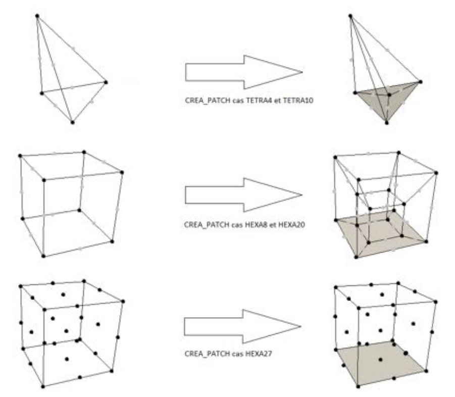
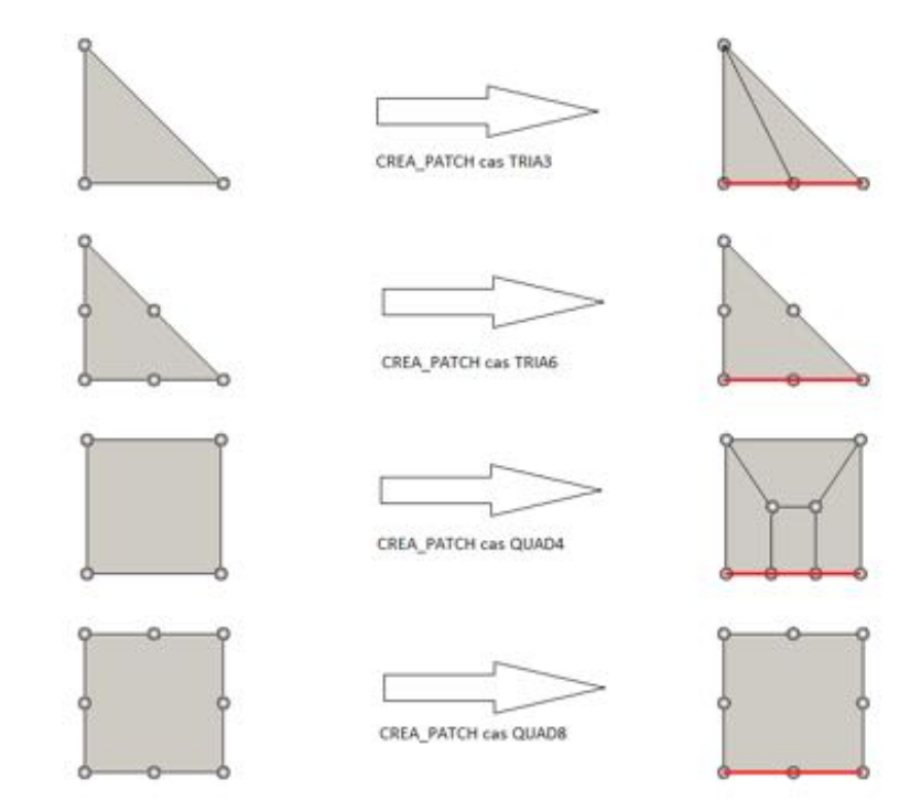
2D case (G. Drouet thesis) 3D case (DECOUPE_HEXA =” HEXA “)
◊ DECOUPE_HEXA
This keyword defines the type of cut used on HEXA8 and HEXA20. By default, these elements are divided into pyramids to limit the number of nodes added. However, using the value HEXA, they are split into HEXA, which can be useful if the introduction of pyramids into the mesh is a problem.
4.19. Operand INFO#
◊ INFO = under
Specify the information printed in the message file (1: no printing, 2: details on the number of meshes created, modified…).
4.20. Operand TITRE#
◊ TITRE = tit
Allows you to specify a title.