2. First step: the mesh#
Here we detail the different steps of the data processing of a typical reinforced concrete structure problem in Code_Aster, for both types of modeling. For each phase, the possible questions to ask and the information to be provided are specified.
2.1. Meshing for model with finite elements of plates#
This choice of mesh offers the advantage of simplicity; however, it involves arbitrariness, because the coordinates of the formwork planes are often used and not the exact position of the middle sheets of the walls and the floors. This also has the disadvantage of counting twice the volume that is at the intersection of the two planes (so in modeling we will count the mass twice and we will exaggerate the ranges).
It is assumed that two planes meshed in surface meshes (floor and wall) intersect along a line that belongs to the mesh of the structure.
To model the junction between plane structural elements more precisely, it is therefore proposed to predict the mesh of the « core » volume of the junction, in the form of a parallelepiped with transverse dimensions identical to the true thicknesses of the connected plane structural elements.
On this volume a mesh will be produced in a single band of hexahedral meshes with 8 knots HEXA8. The border transverse planes between these cells will contain the end nodes of the plane cells of the geometry of the plane structural elements.
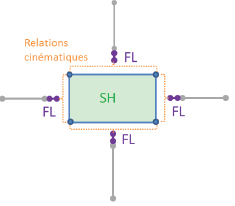
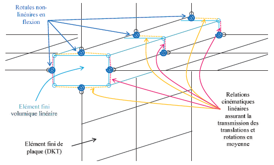
Figure 2.1-a :: **Implementation of the discrete nonlinear model in flexure of a junction between two walls and two floors (current situation). Left: cross-sectional view (plan:math:`(x,y)`**); right: perspective view. **